


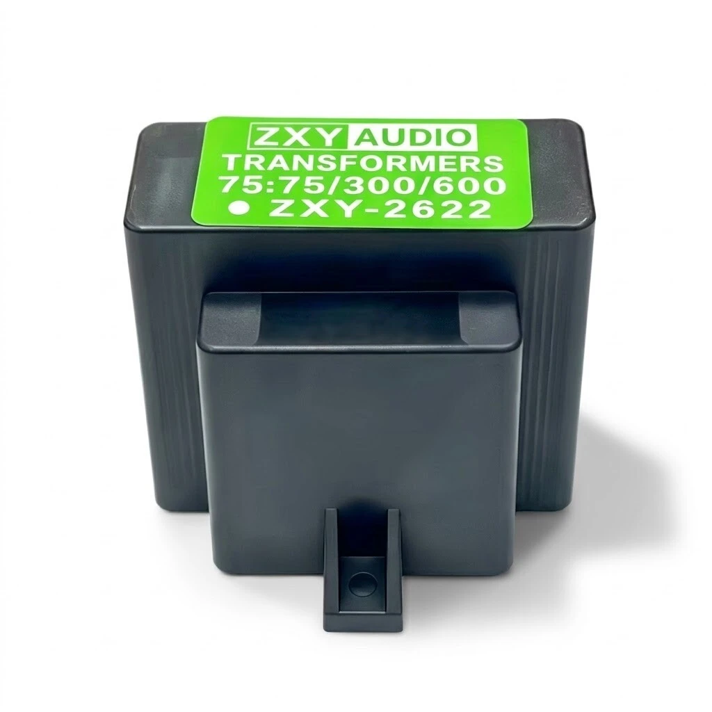
ZXY-2622 75:75/300/600 Ohm Audio Isolation Transformer, Shielded Chassis-Mount Line Transformer with Tapped Secondary
A 75 ohm line isolation transformer with three secondary taps. The primary is one winding on pins 2 and 3, and the secondary is one winding brought out at three points, so a 75, 300 or 600 ohm line can be driven from the same part. Between the windings there is no conductive path, which is the whole point of the device, because it is the path between two earthed chassis that carries the hum. A shield pin and a case pin let the screening be tied where the layout wants it. This is a signal component: the 1000 V AC figure is a winding-to-winding test, not a rating to put mains across.
- Impedance ratio 75 : 75 / 300 / 600 ohm, each tap within plus or minus 10 percent into a 75 ohm load.
- Turns ratio 1 : 1 / 2 / 3 within plus or minus 0.5 percent, pins 2-3 against pins 8-9, 8-10 and 8-11.
- Response 30 Hz to 20 kHz within plus or minus 0.4 dB at a 2 Vrms reference.
- THD 0.07 percent at 1 kHz and +4 dB; maximum 30 Hz input 30 dBu at 1 percent distortion.
- Hi-pot 1000 V AC at 50 Hz, 5 mA for 60 s between pins 2-3 and pins 8-11.
- 63.3 mm body, 48.5 mm deep, 56.5 mm high, ears at 59 mm centres with 3.8 mm holes.
1. Product Name
ZXY-2622 is a shielded, chassis-mount audio isolation transformer with a 75 ohm primary and a tapped secondary giving 75, 300 and 600 ohm. The label on the case reads ZXY AUDIO, TRANSFORMERS, 75:75/300/600 and ZXY-2622. Behind it sits customer drawing G2525, edition A/0, dated 6 November 2025, which also gives the manufacturer's own part name as ZXY2600-75:75/300/600. Three identifiers describe one component: the marking, the drawing number and the house part name. Quote any of them and the other two should be understood.
Twelve pins run in two rows of six on a 35.5 mm row pitch, and two ears 59 mm apart take the screws. That combination is what makes it a chassis part rather than a board part: the ears carry the mechanical load, the pins carry the signal, and the case can be bolted to a metal panel without the winding being tied to that panel unless pin 5 is wired to it. The photographs show it screwed down inside an amplifier next to a circuit board, and wired point to point in a valve chassis, which is how the ears are meant to be used.
2. What It Does
Two pieces of equipment on the same mains are joined by their safety earths, and the shield of the cable between them closes a loop. Current in that loop appears across the signal as hum at the mains frequency and its harmonics, and no amount of screening inside either box removes it, because the loop runs outside both boxes. A transformer breaks the loop: the signal crosses by induction and the earth path does not exist. A 1:1 winding is used where the level must not change, so the receiving stage sees the impedance it saw before. The same break stops digital hash from travelling between a converter and an amplifier that share a ground.
Seventy-five ohm is not an audio convention in the way 600 ohm is. It is the standard impedance of unbalanced broadcast and installed AV wiring, the same number used for video and for 75 ohm digital audio, so a transformer with a 75 ohm primary is the part that sits at the edge of that world. What makes this one flexible is the other side: instead of a single secondary it is tapped, so the same unit can hand a 75 ohm source to a 300 or 600 ohm input without a second part number in the stores.
3. The Tapped Secondary
The three ratios are not three windings. They are one winding with taps counted from pin 8 as the common terminal: 8-9 gives 1:1, 8-10 gives 1:2 and 8-11 gives 1:3. Because the ratios land exactly on one, two and three within half a percent, the three sections between the taps must be equal in turns, so 8 to 9, 9 to 10 and 10 to 11 each carry the same number of turns as the primary. That is worth knowing when wiring, because it means the taps are evenly spaced electrically rather than trimmed to suit particular loads.
| Tap, pins | Turns, primary : secondary | Impedance into 75 ohm | Level change |
|---|---|---|---|
| Pins 8-9 | 1 : 1 | 75 ohm | 0 dB |
| Pins 8-10 | 1 : 2 | 300 ohm | +6.0 dB |
| Pins 8-11 | 1 : 3 | 600 ohm nominal | +9.5 dB |
| Pins 4 and 5 | not a winding | shield and case | not a signal path |
Picking a higher tap does not keep the level the same. Impedance matching by transformer is a turns-ratio step, so a 1:2 tap lifts the voltage by about 6 dB and a 1:3 tap by about 9.5 dB, and the source sees the load divided by the square of the ratio. If the receiving stage has its own gain the difference is absorbed there; if it does not, the tap choice changes the operating level as well as the match.
4. Construction and Screening
The housing is a moulded case in dark grey with a recessed face on top for the rating label and a stepped shoulder on the front, and the mounting ear is drawn as part of the same moulding. Screening has two pins of its own: pin 4 is named as the shield and pin 5 as the metal case, so the two can be joined at one point or taken separately, and whether the metal case is bonded to the panel is a wiring decision rather than a mechanical one, because the ear itself is moulded. In a chassis build the usual arrangement is pin 5 to the panel where the loop is broken and the shield to the end where the hum measures lowest, but the drawing prescribes neither.
5. Electrical Specifications
The electrical page of G2525 is short and every line of it is a measured characteristic rather than a marketing claim. Impedance is quoted at 75 ohm on three taps to ten percent, turns ratio to half a percent, response over the audio band at a 2 Vrms reference, distortion at a single frequency and level, and hi-pot as a winding-to-winding test at 1000 V AC for a minute. That is a workable small-signal set. What it leaves out is anything about the winding itself, and for a line transformer those omissions are the ones a designer notices first.
| Parameter | Specification | Note |
|---|---|---|
| Impedance ratio, 75 ohm load | 75 / 300 / 600 ohm, each plus or minus 10 percent | Three taps on one secondary |
| Turns ratio, pins 2-3 : 8-9 / 8-10 / 8-11 | 1 : 1 / 2 / 3, plus or minus 0.5 percent | The quantity that is tightened |
| Frequency response | 30 Hz to 20 kHz, plus or minus 0.4 dB | At a 2 Vrms reference; header also prints plus or minus 1 dB |
| Maximum 30 Hz input level | 30 dBu at 1 percent THD | About 24.5 Vrms, derived from the dBu definition |
| Harmonic distortion | 0.07 percent at 1 kHz, +4 dB | The +4 dB reference is not named |
| Dielectric strength | 1000 V AC, 50 Hz, 5 mA, 60 s | Pins 2-3 to pins 8-11 |
| DC resistance | Not stated | No winding resistance published |
| Inductance | Not stated | No magnetising inductance published |
| Insertion loss | Not stated | No through loss published |
| Operating temperature | Not stated | No ambient range published |
Two of the entries need reading with care. The response line in the drawing prints a reference of 2 Vrms with plus or minus 1 dB in brackets and then a result of plus or minus 0.4 dB, so the one decibel is attached to the reference condition and the 0.4 dB is the product figure; the description carries both without separating them. The distortion line gives +4 dB with no reference named, and +4 dBu and +4 dBV differ by 2.2 dB, which puts the test level at either about 1.23 Vrms or about 1.58 Vrms.
6. Mechanical Dimensions
The outline is dimensioned in four views, which is more than most parts in this class supply. Front and side give the envelope, the bottom view gives the pin rows and the ear positions, and the top view gives the label footprint. Everything needed to lay out a panel is present except the one figure the ear detail disagrees with.
| Dimension | Value | Where it is drawn |
|---|---|---|
| Body width | 63.3 mm | Front view |
| Body height | 56.5 mm | Front view |
| Overall width over the ears | 70.4 mm | Side view |
| Depth | 48.5 mm | Side view |
| Mounting ear hole centres | 59 mm | Bottom view |
| Pin row pitch | 35.5 mm | Bottom view |
| Mounting hole diameter | 3.8 mm on the drawing, 4.2 mm on the detail panel | Bottom view against detail panel |
| Pin offset from the edge | 6 mm | Bottom view |
| Side view callout | 1 mm, drawn without a name | Side view |
| Weight | Not stated | Not published |
The 35.5 mm figure is the distance between the two pin rows, and 59 mm is the distance between the two ear holes; they are not alternatives for the same measurement. The 6 mm is the offset from the edge of the moulding to the first pin in the row, which is what a footprint needs in order to place the pad field under the case.
7. Application
The intended use is a 75 ohm line that has to reach equipment on a different ground potential, or a 75 ohm source that has to feed a 300 or 600 ohm input. Broadcast and installed AV racks are the obvious homes: a 75 ohm tie line between rooms, a monitor feed that hums when it is patched, a console output into a house system at 600 ohm. The same part answers the older studio problem of a 600 ohm line that picks up noise along a long cable, because the break at the transformer removes the loop and the 1:1 tap leaves the level alone.
Test and measurement is the other natural fit. An isolated branch in a bench instrument stops a ground loop from putting mains-frequency current through a signal lead, and the three taps let one stock item serve both a 75 ohm instrument output and a 600 ohm monitor input. Discrete builds use it the same way: the second scene shows it screwed to a valve preamplifier chassis, where the metal case and the separate shield pin are the reason it can sit close to a transformer feeding a rectifier without the two talking.
8. Ordering and Marking
Buy against drawing G2525, edition A/0, dated 6 November 2025, whose alteration record shows a single entry, first formulation on that date. The drawing states that measurement data is available on request, which is the route to the response curve, the distortion sweep and the hi-pot record rather than a promise printed on a page. Alternative lead lengths, tap combinations and mounting variants are offered on request, so a different tap set is a custom build against a new drawing rather than a variant of this one.
The case carries the ZXY AUDIO name, the ratio 75:75/300/600 and the model ZXY-2622, and the description states that the case marking includes CCC, CE, RoHS and UL conformity marks. In the supplied images the four marks appear together only on the composite product shot, where they are laid out above the transformer on a white band; the close-up of the moulded case shows the green label and no marks. That is a presentation difference rather than a claim of difference, but a buyer who needs the marks on the part should confirm what is printed where, and ask for the certificate numbers behind all four.
| Item | Status | Why it matters here |
|---|---|---|
| Mounting hole | 3.8 mm or 4.2 mm | Two drawings of the same ear disagree; one decides the drill and the screw |
| Second impedance tap list | 75, 300 and 600 only | The drawing file name adds a 15 that no drawing, label or sentence repeats |
| Pins 1, 6, 7 and 12 | Not assigned | Twelve pins, eight named; the other four are unaccounted for in every document |
| +4 dB reference | Unnamed | dBu and dBV differ by 2.2 dB, so the distortion level is ambiguous |
| DC resistance, inductance | Not published | The two numbers a 75 ohm match is normally judged on |
| Operating temperature | Not published | Decides whether the part can sit next to a valve or a heatsink |
| Certificate numbers | None printed | Four marks, no file numbers behind them |
| Price, MOQ, lead time, packing | Not in this material | Commercial terms are quoted separately |