
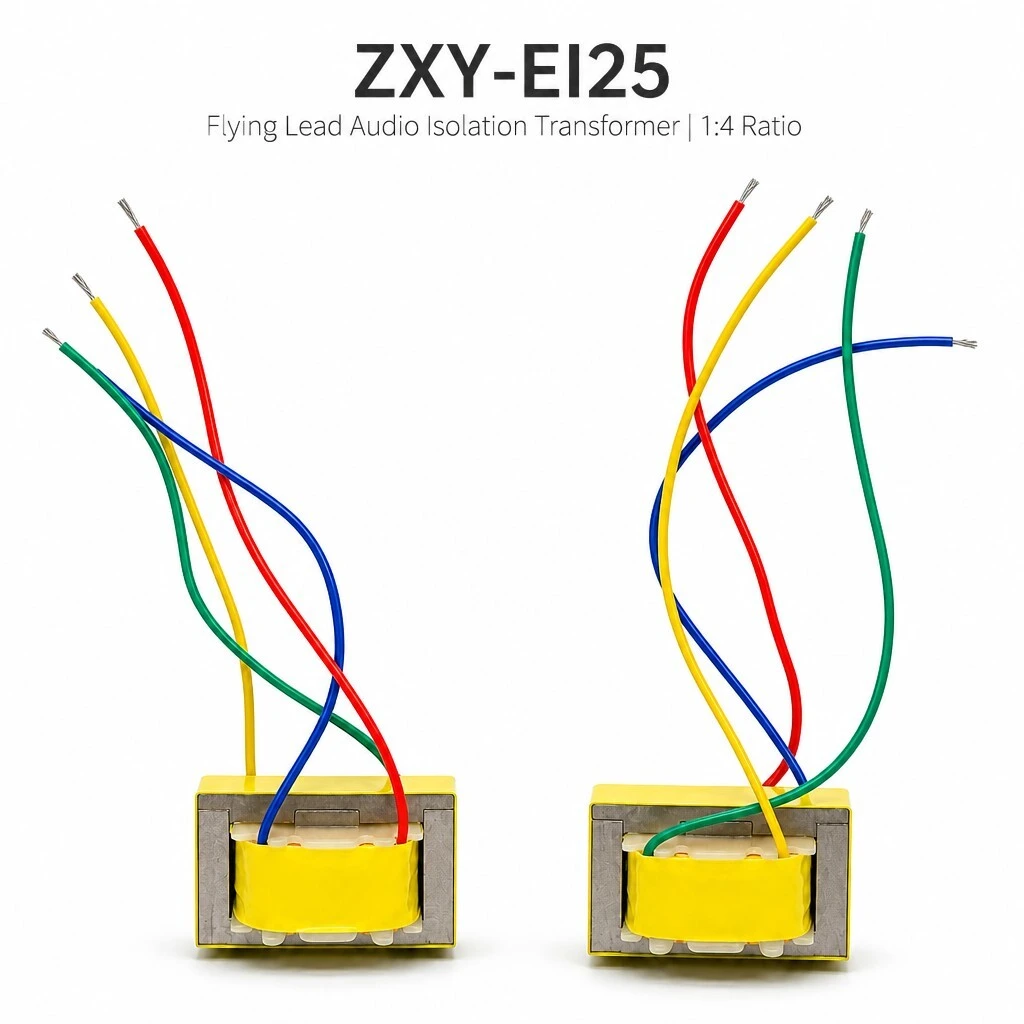
ZXY-EI25 Flying Lead Audio Isolation Transformer, 1:4 Turns Ratio, 50 Hz-20 kHz, EI25 Laminated Core
ZXY-EI25 is a flying-lead audio isolation transformer built on an EI25 laminated core, wound to a 1:4 turns ratio and covering 50 Hz to 20 kHz. Two isolated windings break the ground path between equipment, which is what removes ground-loop hum and protects the output stage on the other side of the barrier. Leads are tinned at the ends, so the part is wired into a harness rather than reflowed onto a land pattern.
- EI25 laminated core, two isolated windings wound to a 1:4 turns ratio
- Inductance at 1 kHz / 0.3 V: 56 mH min primary, 800 mH min secondary
- DCR at 25 °C: 1.6 Ω and 17 Ω, ±15 %
- Hi-pot 1,500 V at 1 mA for 60 s
- Frequency range 50 Hz to 20 kHz, low-distortion design
- Flying leads with tinned ends for flexible routing
- Body 26.0 × 19.0 mm, height 14.8 mm, per the outline drawing
1. Product Name
ZXY-EI25, a flying-lead audio isolation transformer built on an EI25 laminated core. Its two windings are isolated and wound to a 1:4 turns ratio. At 1 kHz and 0.3 V the primary measures 56 mH min and the secondary 800 mH min; DC resistance at 25 °C is 1.6 Ω on the primary and 17 Ω on the secondary, ±15 %. The part covers 50 Hz to 20 kHz and is designed for low distortion across that band, which is why it is described as both a voice and a data coupling transformer.
Two windings, one barrier. The windings are separated, so the signal crosses while the ground path between the two pieces of equipment does not. That is the whole point of the part: it removes the AC hum that system grounding puts on a signal line, and it keeps a fault on one side away from the output stage on the other. Polarity is marked on both windings and defined by the schematic reproduced in the next section.
2. Construction & Materials
The core. An EI25 laminated core, which is the core the specification names. The inductance figures quoted on this page, 56 mH min on the primary and 800 mH min on the secondary, are measured with it at 1 kHz and 0.3 V, and they are the numbers to check a delivered part against.
The windings and their polarity. Two isolated windings, 1:4. The specification defines polarity by the approved schematic, and the schematic supplied with this product is reproduced below: each winding carries a polarity dot at the same end of the symbol, and the two windings sit either side of the insulation barrier. The source does not assign lead colours to windings, so take the winding-to-colour mapping from the schematic that ships with the order rather than from a photograph.
The termination. Flying leads with tinned ends, so the part is wired into a harness or a terminal block instead of being reflowed onto a land pattern. Tinned ends are solderable as supplied, without stripping and re-tinning on the bench, and the lead length gives the routing freedom that a pinned part does not have. Lead length and wire gauge are not declared in the source and are therefore not quoted on this page.
3. Feature
Flying-lead build on an EI25 laminated core. The part is wired in through leads rather than a land pattern, so the mounting position is set by the harness and not by a PCB footprint.
Turns ratio 1:4. The secondary carries four times the turns of the primary, and the two windings are isolated from each other.
Inductance 56 mH min and 800 mH min at 1 kHz / 0.3 V. Primary and secondary respectively, verified on both windings at the stated condition.
DCR 1.6 Ω and 17 Ω at 25 °C, ±15 %. Primary and secondary respectively; the tolerance is declared, so a delivered part can be checked against a limit rather than against a nominal.
Hi-pot 1,500 V, 1 mA, 60 s. A dielectric test at a declared voltage, a declared leakage limit and a declared duration.
Frequency range 50 Hz to 20 kHz. Voice and programme material in one band, which is why the part is described as both a voice and a data coupling transformer.
Two isolated windings with polarity marking. Polarity is defined by the approved schematic, so phase can be held between units in a build.
Flying leads with tinned ends. Solderable as supplied, without a strip-and-re-tin operation on the bench.
Low distortion across a wide frequency response. Speech clarity and audio fidelity from one part, as the source puts it.
Body 26.0 × 19.0 mm, height 14.8 mm. Per the outline drawing: compact enough to sit inside an audio module or behind a connector panel.
4. Advantage
The signal crosses, the ground does not. The isolated 1:4 windings transfer the signal while breaking the ground path between the two pieces of equipment, which is the barrier doing the work rather than a filter.
Ground-loop hum removed at the cause. AC hum produced by system grounding is stopped by the barrier instead of being trimmed out downstream.
Front-end output stages protected. A fault on one side does not reach the output stage of the equipment on the other, which is what the source means by protecting against burnout.
Balanced and unbalanced lines both covered. External interference on either kind of transmission line is reduced by the same barrier.
Installed by lead, not by footprint. The flying leads fit multiple wiring scenarios, which is the practical advantage over a pinned part when the harness is already designed.
One part for voice and data. A single 50 Hz to 20 kHz transformer covers the coupling job in both, so the bill of materials does not need two parts.
Customized designs to requirement. Alternative windings are available on request; the series build is the 1:4 part described here.
5. Application
Professional audio. Lavalier, camera and instrument microphones, mic preamps and audio isolation modules.
Audio systems. High-end speakers, home theatre and car audio, for signal isolation and noise elimination.
Communication equipment. Telephones, fax machines, IP voice terminals and modems, for signal coupling.
Industrial and broadcast systems. Public address and conference systems, for audio isolation and transmission.
6. Specifications
The tables below reproduce the specification as declared for ZXY-EI25, given in the source as the ZXYEI25 flying-lead version. Where the source gives no figure, the cell says so instead of carrying a number in from another series.
6.1 Summary
| Item | Specification | Note |
|---|---|---|
| Model | ZXY-EI25 flying lead | ZXYEI25 flying-lead version |
| Reference part number | B2316 | Reference the source gives; confirm on order |
| Core | EI25 laminated core | Declared as laminated |
| Turns ratio | 1:4 | Two isolated windings |
| Inductance | 56 mH min / 800 mH min | Primary / secondary, at 1 kHz and 0.3 V |
| DCR at 25 °C | 1.6 Ω / 17 Ω | ±15 %, primary / secondary |
| Hi-pot | 1,500 V, 1 mA, 60 s | AC or DC not declared |
| Frequency range | 50 Hz to 20 kHz | Low-distortion design intent |
| Windings | Two isolated windings | Polarity marked per schematic |
| Termination | Flying leads with tinned ends | Lead length and gauge not declared |
| Body | 26.0 × 19.0 mm, height 14.8 mm | Per the outline drawing |
| Options | Customized design | Alternative windings on request |
6.2 Electrical
| Parameter | Specification | Test condition |
|---|---|---|
| Turns ratio | 1:4 | Primary to secondary |
| Inductance, primary | 56 mH minimum | At 1 kHz and 0.3 V |
| Inductance, secondary | 800 mH minimum | At 1 kHz and 0.3 V |
| DC resistance, primary | 1.6 Ω ±15 % | At 25 °C |
| DC resistance, secondary | 17 Ω ±15 % | At 25 °C |
| Hi-pot | 1,500 V at 1 mA | For 60 s; AC or DC not declared |
| Frequency range | 50 Hz to 20 kHz | No tolerance in dB declared |
| Isolation | Two isolated windings | Ground path broken between equipment |
6.3 Materials and construction
| Item | Specification | Declared property |
|---|---|---|
| Core | EI25 laminated core | Laminated, as declared |
| Windings | Two isolated windings | 1:4 turns ratio, polarity marked |
| Termination | Flying leads, tinned ends | Tinned for direct soldering |
| Insulation class | Not declared | Request it with the drawing |
| Encapsulation | Not declared | Request it with the drawing |
6.4 Mechanical and termination
| Item | Value | Note |
|---|---|---|
| Body length | 26.0 mm | Per the outline drawing |
| Body width | 19.0 mm | Per the outline drawing |
| Body height | 14.8 mm | Per the outline drawing |
| Termination | Flying leads, four shown | Lead count is not stated in the source |
| Lead length and gauge | Not declared | Confirm on the drawing |
| Weight | Not declared | Confirm on the drawing |
| Mounting | Wired by flying leads | No land pattern is declared |
6.5 Quality and testing
| Item | Requirement | Condition |
|---|---|---|
| Hi-pot | 1,500 V, 1 mA, 60 s | Tested per unit |
| Inductance | 56 mH min / 800 mH min | Verified at 1 kHz / 0.3 V on both windings |
| DCR | 1.6 Ω / 17 Ω | ±15 %, at 25 °C |
| Polarity | Marked per schematic | Defined by the approved schematic |
| Electrical data source | EI25 product specification | Measured at 25 °C |
7. Ordering
The part is ordered as ZXY-EI25, described in the specification as the ZXYEI25 flying-lead version. The specification also lists a reference part number, B2316; it is quoted here as the reference the source gives, not as an independently verified ordering code, so confirm it against the ZXY order confirmation. Alternative windings and customized designs are available on request, and a customized build is quoted against a drawing or a sample rather than against this table.
Certification: no certificate naming ZXY-EI25 was supplied with this description, so no compliance claim is made on this page and the render that carries a row of certification badges was not used. If the listing needs a certificate, quote the number from the certificate itself.
Brand / manufacturer: ZXY, Shenzhen Zhixiangyuan Electronics Co., Ltd. http://www.zxycoil.com