
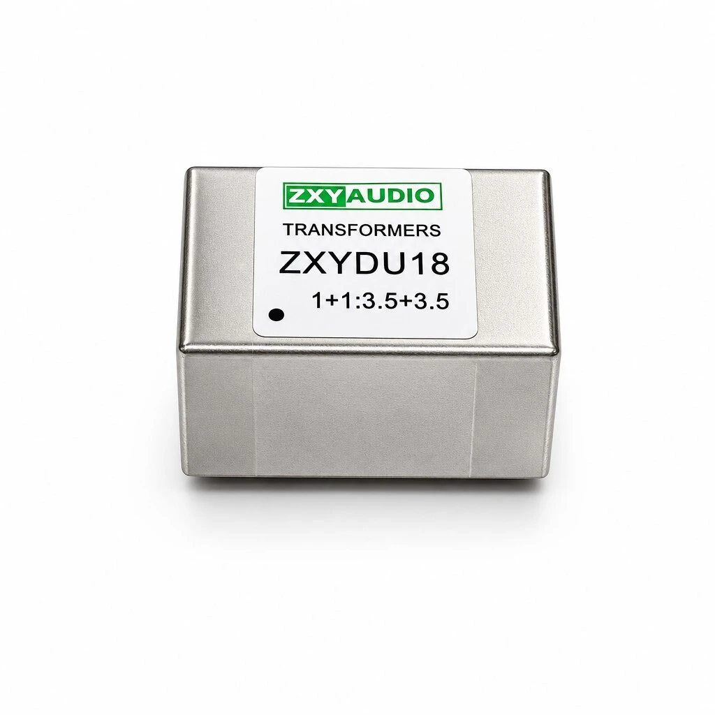
ZXY-DU18 Permalloy Audio Isolation Transformer, 1+1:1+1 and 1+1:3.5+3.5, 10 Hz to 100 kHz, DIP
ZXY-DU18 is a wideband audio isolation transformer in a sealed permalloy alloy housing with DIP through-hole mounting. Two winding variants are available, 1+1:1+1 and 1+1:3.5+3.5. Frequency response is ±0.5 dB from 10 Hz to 100 kHz at 1 % THD against a −6 dB 1 kHz reference, the maximum 50 Hz input level is +13 dBu, and the hi-pot rating is 1,250 V tested at 1 mA for 60 s. Outline 38.5 mm by 24.5 mm, 22.0 mm high, on 8 pins in two rows of four at 5.0 mm pitch.
- 10 Hz to 100 kHz within ±0.5 dB, at 1 % THD against a −6 dB 1 kHz reference
- Maximum 50 Hz input level +13 dBu, for line-level headroom at the bottom of the band
- Two winding variants: 1+1:1+1 and 1+1:3.5+3.5, in the same can and outline
- DCR from 35+35 Ω max to 360+360 Ω max depending on the variant, at 25 °C
- Hi-pot 1,250 V at 1 mA for 60 s between windings
- Sealed permalloy alloy housing, E1 (can) and E2 (core); 38.5 × 24.5 mm, 22.0 mm high
1. Product Name
ZXY-DU18, a wideband audio isolation transformer in a sealed permalloy alloy housing with DIP through-hole mounting. Eight pins in two rows of four at 5.0 mm pitch, outline 38.5 mm by 24.5 mm and 22.0 mm high. Two winding variants are supplied, 1+1:1+1 and 1+1:3.5+3.5, with the DC resistance and the turns ratio differing between them and everything else shared.
One can, two builds. The outline does not change between the variants, so a board can be laid out once and populated as either ratio. What changes is the winding and the copper: the 1+1:1+1 build runs 56+73 Ω on the primary side and 65+76 Ω on the secondary, the 1+1:3.5+3.5 build runs 35+35 Ω and 360+360 Ω.
2. Construction & Materials
The housing. A sealed permalloy alloy can, given in the specification as E1 (can) and E2 (core). A permalloy can is a magnetic shield as much as a box: it closes the magnetic circuit against fields coming from outside, and it protects the winding inside from handling. Because the can is sealed rather than an open frame, the part presents a metal block to the board and to whatever sits beside it.
The pins. Eight through-hole pins, four in a row at each end of the can, on 5.0 mm pitch. Through-hole rather than SMD is the right choice at this size for two reasons: a 22.0 mm tall can on cable-side equipment puts a bending load on its terminations that a gull wing does not take well, and the lead spacing is coarse enough that a through-hole layout needs no special land pattern.
The winding. Two winding sections per side, which is what the 1+1 notation describes: the primary and the secondary are each split into two halves that are joined at the pin pair, so the resistance across pins 1-4 and pins 5-8 is quoted as the sum of the halves. In the 1+1:1+1 build the two primary halves are not equal, 56 Ω against 73 Ω, while the 1+1:3.5+3.5 build uses equal halves of 35 Ω and 360 Ω.
The bevel edge visible on the can is where the two halves of the housing meet and are sealed, and the label carries the ratio the part is wound for, so a populated tray can be checked without measuring.
3. Feature
Wideband, 10 Hz to 100 kHz. The response is held within ±0.5 dB across four decades, measured at 1 % THD against a −6 dB 1 kHz reference. That covers the audio band and the ultrasonic content above it in one part.
Two winding variants. The same can and core are wound as 1+1:1+1 for straight isolation and as 1+1:3.5+3.5 where the signal has to be stepped up or matched, so one footprint serves two circuit roles.
+13 dBu at 50 Hz. The maximum 50 Hz input level is the headroom figure: it is the level the core will take at the bottom of the band before the response starts to fold, and it is what makes the part usable on line-level signals rather than microphone levels.
Sealed permalloy alloy housing. The winding sits inside a sealed can rather than an open frame, so the magnetic circuit is closed against external fields and the coil is protected from handling and from the board environment.
DIP through-hole, 8 pins. Two rows of four pins on 5.0 mm pitch, which is a footprint a through-hole layout can take without a custom land pattern.
Isolation stated as a test. 1,250 V at 1 mA for 60 s between windings, applied to every unit rather than quoted as a type test.
4. Advantage
It removes the hum at its source. The transformer breaks the signal-path ground connection instead of filtering the result. Where a ground loop is injecting AC hum, removing the loop is the fix; attenuating the hum afterwards is a compromise.
Protects the stage in front of it. Because the two sides are electrically separate, a fault or a DC offset on one side cannot reach the output stage of the equipment on the other, which is what the document means by preventing burnout of front-end equipment.
Balanced and unbalanced both benefit. The sealed can reduces what the winding picks up from neighbouring fields, which matters most on an unbalanced run where there is no common-mode rejection to fall back on.
Flat where it counts. ±0.5 dB from 10 Hz to 100 kHz means the part is not the element that limits the system's bandwidth, so the design margin can be spent on the converters and the amplifier instead.
One can, two ratios. A 1+1:1+1 build and a 1+1:3.5+3.5 build share the same outline, so a board can be laid out once and populated either way.
Through-hole that survives rework. A sealed can on 5.0 mm pitched pins takes the mechanical load of a cable-side connection better than a small SMD body, which is why the package is DIP on a part used at line level.
5. Application
Hi-Fi and audiophile systems. Between a source and a preamplifier, or between a preamplifier and a power amplifier, where a ground loop is audible as hum and the signal has to cross a barrier intact.
Home theatre and multi-channel systems. Each channel can be isolated independently, which is what stops one earthed source from putting hum on every other channel in the rack.
Car audio. Between a head unit and an amplifier where the two are earthed at different points of the chassis.
Mixing console outputs. On the isolation output of a console, so a stage box or a recorder can be connected without tying its ground to the console's.
Multi-channel isolation output circuits. Where a number of outputs leave one chassis and each has to stay separated from the others.
6. Specifications
The data below is the specification for ZXY-DU18, reproduced as declared.
6.1 Summary
| Parameter | Specification | Note |
|---|---|---|
| Model | ZXY-DU18 | Sealed permalloy alloy housing |
| Type | Wideband audio isolation transformer | DIP through-hole |
| Turns ratio | 1+1:1+1 and 1+1:3.5+3.5 | Two standard variants |
| Max 50 Hz input level | +13 dBu | Line-level headroom |
| Frequency response | ±0.5 dB | 10 Hz to 100 kHz at 1 % THD |
| Reference | −6 dB at 1 kHz | Response referred to this point |
| Hi-pot | 1,250 V, 1 mA, 60 s | Between windings |
| Housing | Sealed permalloy alloy | E1 (can), E2 (core) |
| Mounting | DIP through-hole, 8 pins | Four per row, 5.0 mm pitch |
| Outline | 38.5 × 24.5 mm, 22.0 mm high | Per drawing |
| Function | Voice and data coupling | Ground-loop isolation |
6.2 Electrical
| Parameter | Specification | Test condition |
|---|---|---|
| Maximum 50 Hz input level | +13 dBu | At 50 Hz |
| Frequency response | ±0.5 dB | 10 Hz to 100 kHz |
| Distortion at test | 1 % THD | Response measured at this distortion |
| Reference level | −6 dB at 1 kHz | Response curve referred to this point |
| Hi-pot | 1,250 V, 1 mA, 60 s | Between windings |
6.3 DC resistance by variant
| Winding | DCR pins 1-4 | DCR pins 5-8 |
|---|---|---|
| 1+1:1+1 | 56+73 Ω max | 65+76 Ω max |
| 1+1:3.5+3.5 | 35+35 Ω max | 360+360 Ω max |
6.4 Mechanical
| Dimension | Value | Note |
|---|---|---|
| Outline length | 38.5 mm | Per drawing |
| Outline width | 24.5 mm | Per drawing |
| Height | 22.0 mm | Per drawing |
| Terminals | 8 pins, DIP through-hole | Four per row |
| Pin pitch | 5.0 mm | Between adjacent pins of a row |
| Pin rows | One at each end of the can | Row spacing to be read from the drawing |
| Mounting | Through-hole, wave or hand solder | DIP package |
6.5 Quality and testing
| Item | Requirement | Condition |
|---|---|---|
| Condition | All electrical parameters at 25 °C | DCR, input level, response and hi-pot |
| Dielectric strength | 1,250 V at 1 mA for 60 s | Every unit |
| Frequency response | Verified at 1 % THD against a −6 dB 1 kHz reference | 10 Hz to 100 kHz |
| Supply | Factory direct with in-stock delivery | Custom design to customer requirement |
7. Ordering
The part is ordered as ZXY-DU18 with the winding variant stated. The can, the core, the pin-out and the outline are common; the turns ratio and the copper are not, so an order that does not name the variant cannot be checked against a single acceptance table. Factory direct supply with in-stock delivery is stated for the standard builds, and a customized design is available to customer requirement.
Brand / manufacturer: ZXY, Shenzhen Zhixiangyuan Electronics Co., Ltd. http://www.zxycoil.com