loading

ZXY: 26 Years of Excellence as a Leading Transformer and Inductor Manufacturer ・ One-Stop Solutions

ZXY-ED8-10 1:1 Audio Isolation Transformer, 600 Ohm to 400 Ohm Line Matching, ED8X10-2.0H Laminated Core, Gull-Wing Terminals in a 14 mm Package 1
ZXY-ED8-10 1:1 Audio Isolation Transformer, 600 Ohm to 400 Ohm Line Matching, ED8X10-2.0H Laminated Core, Gull-Wing Terminals in a 14 mm Package 2
ZXY-ED8-10 1:1 Audio Isolation Transformer, 600 Ohm to 400 Ohm Line Matching, ED8X10-2.0H Laminated Core, Gull-Wing Terminals in a 14 mm Package 3
ZXY-ED8-10 1:1 Audio Isolation Transformer, 600 Ohm to 400 Ohm Line Matching, ED8X10-2.0H Laminated Core, Gull-Wing Terminals in a 14 mm Package 4
ZXY-ED8-10 1:1 Audio Isolation Transformer, 600 Ohm to 400 Ohm Line Matching, ED8X10-2.0H Laminated Core, Gull-Wing Terminals in a 14 mm Package 5
ZXY-ED8-10 1:1 Audio Isolation Transformer, 600 Ohm to 400 Ohm Line Matching, ED8X10-2.0H Laminated Core, Gull-Wing Terminals in a 14 mm Package 6
ZXY-ED8-10 1:1 Audio Isolation Transformer, 600 Ohm to 400 Ohm Line Matching, ED8X10-2.0H Laminated Core, Gull-Wing Terminals in a 14 mm Package 7
ZXY-ED8-10 1:1 Audio Isolation Transformer, 600 Ohm to 400 Ohm Line Matching, ED8X10-2.0H Laminated Core, Gull-Wing Terminals in a 14 mm Package 8
ZXY-ED8-10 1:1 Audio Isolation Transformer, 600 Ohm to 400 Ohm Line Matching, ED8X10-2.0H Laminated Core, Gull-Wing Terminals in a 14 mm Package 9
ZXY-ED8-10 1:1 Audio Isolation Transformer, 600 Ohm to 400 Ohm Line Matching, ED8X10-2.0H Laminated Core, Gull-Wing Terminals in a 14 mm Package 10
ZXY-ED8-10 1:1 Audio Isolation Transformer, 600 Ohm to 400 Ohm Line Matching, ED8X10-2.0H Laminated Core, Gull-Wing Terminals in a 14 mm Package 1
ZXY-ED8-10 1:1 Audio Isolation Transformer, 600 Ohm to 400 Ohm Line Matching, ED8X10-2.0H Laminated Core, Gull-Wing Terminals in a 14 mm Package 2
ZXY-ED8-10 1:1 Audio Isolation Transformer, 600 Ohm to 400 Ohm Line Matching, ED8X10-2.0H Laminated Core, Gull-Wing Terminals in a 14 mm Package 3
ZXY-ED8-10 1:1 Audio Isolation Transformer, 600 Ohm to 400 Ohm Line Matching, ED8X10-2.0H Laminated Core, Gull-Wing Terminals in a 14 mm Package 4
ZXY-ED8-10 1:1 Audio Isolation Transformer, 600 Ohm to 400 Ohm Line Matching, ED8X10-2.0H Laminated Core, Gull-Wing Terminals in a 14 mm Package 5
ZXY-ED8-10 1:1 Audio Isolation Transformer, 600 Ohm to 400 Ohm Line Matching, ED8X10-2.0H Laminated Core, Gull-Wing Terminals in a 14 mm Package 6
ZXY-ED8-10 1:1 Audio Isolation Transformer, 600 Ohm to 400 Ohm Line Matching, ED8X10-2.0H Laminated Core, Gull-Wing Terminals in a 14 mm Package 7
ZXY-ED8-10 1:1 Audio Isolation Transformer, 600 Ohm to 400 Ohm Line Matching, ED8X10-2.0H Laminated Core, Gull-Wing Terminals in a 14 mm Package 8
ZXY-ED8-10 1:1 Audio Isolation Transformer, 600 Ohm to 400 Ohm Line Matching, ED8X10-2.0H Laminated Core, Gull-Wing Terminals in a 14 mm Package 9
ZXY-ED8-10 1:1 Audio Isolation Transformer, 600 Ohm to 400 Ohm Line Matching, ED8X10-2.0H Laminated Core, Gull-Wing Terminals in a 14 mm Package 10

ZXY-ED8-10 1:1 Audio Isolation Transformer, 600 Ohm to 400 Ohm Line Matching, ED8X10-2.0H Laminated Core, Gull-Wing Terminals in a 14 mm Package

1:1 line isolation, 600 ohm to 400 ohm, plus or minus 0.12 dB over 300 Hz to 4 kHz

A 1:1 audio isolation transformer in a 14 mm laminated package, meant for the point where a 600 ohm line meets a 400 ohm device input. Both windings are specified identically, 105 ohm of DC resistance and 2.0 H of inductance, which is what keeps a 1:1 part balanced instead of merely isolated. The band is quoted where it is used rather than as a headline: plus or minus 0.12 dB from 300 Hz to 4 kHz, 2.3 dB of insertion loss at most, and a return loss that stays above 28 dB down at 300 Hz.

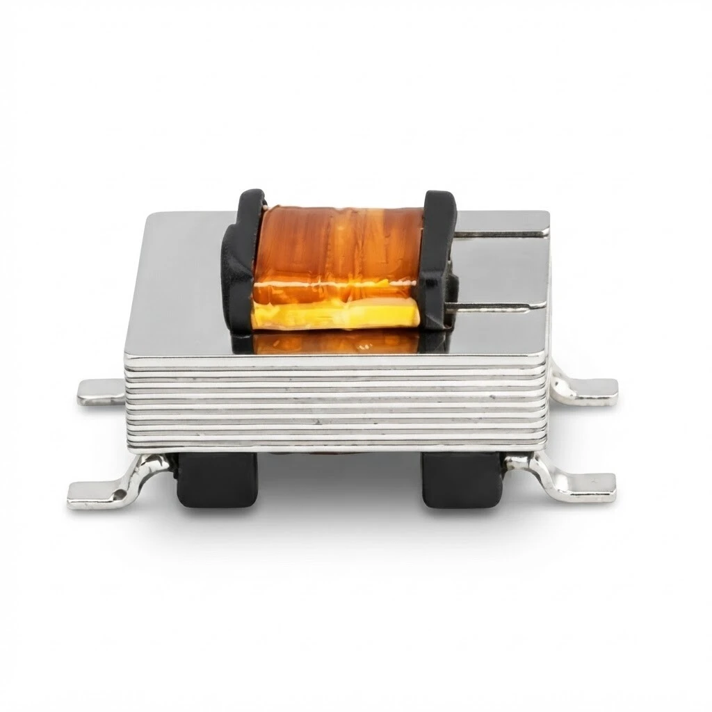
ZXY-ED8-10 in front elevation: the laminated core, the clamp over the winding and the gull-wing terminals, two at each end
KEY HIGHLIGHTS
  • Turns ratio 1:1 within plus or minus 2 percent, winding 1-2 to winding 3-4.
  • DCR 105 ohm on each winding within plus or minus 15 percent; inductance 2.0 H minimum.
  • 600 ohm on 1-2 with a 400 ohm load on 3-4, measured at 1 kHz and 0 dBm.
  • Plus or minus 0.12 dB from 300 Hz to 4 kHz; insertion loss 2.3 dB maximum.
  • Return loss 28 dB minimum at 300 Hz, 35 dB minimum at 1 kHz and at 4 kHz.
  • Hi-pot 1250 V AC at 1 mA for 2 s; laminated E-I core in a 14.1 by 7.95 by 5.0 mm outline.
This is the best specified part in the audio range so far: both winding resistances, the inductance with its test frequency, the impedance with its load, insertion loss, frequency response and return loss at three frequencies are all given with conditions. Two things still need settling before a listing goes live. The photographs and the detail board show gull-wing feet sitting on surface pads, while the outline drawing draws plain tabs and dimensions neither the lead form nor a land pattern, so the footprint has to come from a sample. And the Chinese sheet that travels with this family quotes different part numbers, different inductances, a different hi-pot duration and a different inductance test condition from the English documents.
5.0
Model:
ZXY-ED8-10, type ED8X10-2.0H
Insertion loss:
2.3 dB maximum at 1 kHz
Type:
Audio isolation transformer, 1
Manufacturer:
Shenzhen Zhixiangyuan Electronics Co., Ltd.
Frequency response:
300 Hz to 4 kHz, plus or minus 0.12 dB
Hi-pot:
1250 V AC, 1 mA, 2 s
Turns ratio:
1
Package:
Laminated core, gull-wing terminals
Impedance:
600 ohm to 400 ohm
Brand:
ZXY
design customization

    oops...!

    no product data.

    Go to homepage
    Return loss at 4 kHz
    35 dB minimum
    Return loss at 1 kHz
    35 dB minimum
    Return loss at 300 Hz
    28 dB minimum
    Reference frequency
    1 kHz
    Load condition
    400 ohm on 3-4, 1 kHz, 0 dBm
    DCR winding 3-4
    105 ohm, plus or minus 15 percent
    DCR winding 1-2
    105 ohm, plus or minus 15 percent
    Turns ratio test
    1-2 to 3-4
    Reference temperature
    25 degrees C
    Type
    Audio isolation transformer
    Dielectric strength
    1250 V AC, 1 mA, 2 s
    Frequency response
    plus or minus 0.12 dB, 300 Hz to 4 kHz
    Insertion loss
    2.3 dB maximum
    Turns ratio
    1
    Inductance test
    250 Hz, 0.5 V
    Inductance
    2.0 H minimum, parallel
    Terminals
    Four, gull-wing
    Impedance
    600 ohm on 1-2
    Compliance
    RoHS
    Core
    Laminated E-I

    1. Product Name and Marking

    ZXY-ED8-10 is the product name and ED8X10-2.0H is the type: ED8X10 for the package, which measures 0.555 in by 0.313 in by 0.197 in, and 2.0H for the 2.0 henry minimum inductance. The part carries no printed label. What little marking there is sits on the bobbin between the core and the clamp, where it is too small to read in the photographs and too dark to photograph against the varnish; the only place the type appears in full is on the documents.

    That makes the paperwork the identity of the part, and the paperwork is not one voice. The Chinese sheet that travels with this family is a two-row table for B2161 and B2132, at 1.0 H and 1.2 H, with 125 ohm, 135 ohm and 155 ohm of DC resistance and a hi-pot of 1 mA for 60 seconds. The English description and the specification sheet describe ED8X10-2.0H alone, at 2.0 H, 105 ohm on both windings and a hi-pot of 1 mA for 2 seconds. Both are plausible sheets for a family of 1:1 line transformers; only one of them is this part.

    ZXY-ED8-10 1:1 Audio Isolation Transformer, 600 Ohm to 400 Ohm Line Matching, ED8X10-2.0H Laminated Core, Gull-Wing Terminals in a 14 mm Package 11
    Two units with the bobbin marking called out, together with the core stack and the winding beneath the tape
    Ask which part number the invoice will carry: ZXY-ED8-10, ED8X10-2.0H, or one of the B-series numbers from the Chinese sheet. On a 1:1 transformer the three are electrically interchangeable in most circuits, which is exactly why the mistake survives: a buyer who orders from the family table can receive a 1.0 H part and only find out at low frequency, where the difference between 1.0 H and 2.0 H is audible.

    2. What It Does

    It is a passive 1:1 transformer, two windings on one laminated core, no supply and no active parts. The signal goes in on one winding and comes out on the other with no copper path between them, so a difference in earth potential between two pieces of equipment stops at the core. With a 1:1 ratio the voltage is not meant to change, which is the point: the part is there to break a ground loop and to present 600 ohm to a line and 400 ohm to a device input, not to add or remove level.

    ZXY-ED8-10 1:1 Audio Isolation Transformer, 600 Ohm to 400 Ohm Line Matching, ED8X10-2.0H Laminated Core, Gull-Wing Terminals in a 14 mm Package 12
    The schematic as supplied: 600 ohm line on pins 1 and 2, 400 ohm device on pins 4 and 3, with the polarity dots on the coil ends

    A 1:1 part is harder to get right than a step-down, because both windings have to be the same. The sheet shows that it is: 105 ohm on 1-2 and 105 ohm on 3-4 to the same tolerance, and 2.0 H minimum on both when they are measured in parallel. Matching the two halves is what keeps the balance stable across the band, and balance is what a balanced line relies on to reject what it picks up on the way.

    The polarity dots on the schematic sit at the ends of the coils nearest the core, not beside the pin numbers, so the drawing does not say in so many words which pin is in phase with which. On a line transformer that decides whether a balanced pair stays in phase or comes out inverted, so confirm it with a signal on the first sample rather than reading it off the sheet.

    3. The Winding Pair and the Two Impedances

    Two windings, four terminals, and a naming convention that is worth reading twice. Pins 1 and 2 are one winding and pins 3 and 4 are the other; the schematic draws 1 and 2 on the line side and 4 and 3 on the device side, which is why the ratio is written 1-2 to 3-4 rather than 1-2 to 4-3. The DC resistance is 105 ohm on each winding within plus or minus 15 percent at 25 degrees C, and the inductance is 2.0 H minimum with the two windings tied in parallel, measured at 250 Hz and 0.5 V.

    ParameterValueCondition
    Turns ratio, 1-2 to 3-41:1, plus or minus 2 percentRatio test
    DCR, winding 1-2105 ohm, plus or minus 15 percent25 degrees C
    DCR, winding 3-4105 ohm, plus or minus 15 percent25 degrees C
    Inductance, parallel2.0 H minimum250 Hz, 0.5 V, windings tied
    Impedance600 ohm on 1-21 kHz, 0 dBm, 400 ohm on 3-4
    Dielectric strength1250 V AC, 1 mA, 2 sPrimary to secondary
    ComplianceRoHSMaterials and process

    The two impedances are not a ratio, they are an interface: 600 ohm is what a line looks like and 400 ohm is what the device input looks like. The sheet states it as 600 ohm on 1-2 measured at 1 kHz and 0 dBm with 400 ohm on 3-4, which is the only way the number means anything; measured open circuit it would read higher and tell a designer nothing about the circuit it will sit in.

    ZXY-ED8-10 1:1 Audio Isolation Transformer, 600 Ohm to 400 Ohm Line Matching, ED8X10-2.0H Laminated Core, Gull-Wing Terminals in a 14 mm Package 13
    Two units from above: the laminated stack, the clamp and the four terminals, two at each end
    The inductance condition is worth keeping in view when comparing suppliers. 2.0 H is quoted in parallel, at 250 Hz and 0.5 V; a competitor quote of 2.0 H per winding at 1 kHz is a different measurement and a different part, and one of them will sound thin at 50 Hz. Ask for the test frequency, the drive level and the connection whenever an inductance figure is quoted for a line transformer.

    4. What the Signal Sees

    Three numbers describe the part from the signal's point of view and this sheet gives all three, each with a condition. Frequency response is plus or minus 0.12 dB from 300 Hz to 4 kHz against a 1 kHz reference, which is flat enough that the transformer is not the thing colouring the channel. Insertion loss is 2.3 dB maximum at 1 kHz and 0 dBm into a 400 ohm load, which is the price of the copper and the core and is normal for a part this size. Return loss is 28 dB minimum at 300 Hz and 35 dB minimum at 1 kHz and 4 kHz, which says the input actually looks like 600 ohm across the band rather than only at the design frequency.

    ParameterValueCondition
    Frequency responseplus or minus 0.12 dB300 Hz to 4 kHz, referred to 1 kHz
    Insertion loss2.3 dB maximum1 kHz, 0 dBm, 400 ohm load
    Return loss at 300 Hz28 dB minimumSame load
    Return loss at 1 kHz35 dB minimumSame load
    Return loss at 4 kHz35 dB minimumSame load
    Read the three return loss figures as a curve rather than as three points. 28 dB at 300 Hz against 35 dB an octave and a half higher is the shape you expect from a transformer whose inductance is finite: the match degrades as the impedance of the winding falls with frequency. A part quoted at 35 dB flat from 300 Hz either has more inductance or is quoting the mid-band figure as if it covered the band.

    The band itself is 300 Hz to 4 kHz, which is the voice band and not the full audio band. That is not a limitation hidden in the small print, it is the application: this is a line and intercom part, and quoting it to 20 kHz would be a different design with a different core. If a programme path needs 20 Hz to 20 kHz, this is the wrong family, and the sheet is honest enough to say so by stating the band it was measured over.

    5. Construction, Glue and Terminals

    The build is a laminated E-I core clamped over a glue-dispensed bobbin, with the winding covered by polyimide tape and the terminals formed as gull-wing feet, two at each end. The glue is the detail that gets mis-described most often: the English description calls the part potted, which suggests a filled can, while the photographs show an open clamp with adhesive at the core joint and around the bobbin where it meets the core. The second reading is the one the pictures support, and it is also the one that matters for the buyer, because a clamped core can be re-clamped and a potted one cannot.

    ZXY-ED8-10 1:1 Audio Isolation Transformer, 600 Ohm to 400 Ohm Line Matching, ED8X10-2.0H Laminated Core, Gull-Wing Terminals in a 14 mm Package 14
    Detail panel from the supplier: the gold-plated terminal, the polyimide tape over the winding, and the laminated core stack
    One inset in that panel, labelled Laminated Cayer, is a printed-circuit cross-section rather than a lamination: the parallel traces with their vias are on a board. It is part of the supplied set and is reproduced as it stands, but replace it before the panel goes to print, because a buyer who looks closely will read it as a mistake about the product rather than about the picture.
    ZXY-ED8-10 1:1 Audio Isolation Transformer, 600 Ohm to 400 Ohm Line Matching, ED8X10-2.0H Laminated Core, Gull-Wing Terminals in a 14 mm Package 15
    The same build from three quarters, with the clamp ends and the terminal feet in view
    PinWindingNote
    1Winding 1-2, one end600 ohm line side; 105 ohm to pin 2
    2Winding 1-2, other endThe pair is the line winding on the schematic
    4Winding 3-4, one end400 ohm device side; 105 ohm to pin 3
    3Winding 3-4, other endDrawn below pin 4 on the schematic
    Two descriptions of the terminal disagree in a way that affects the footprint. The detail panel calls them SMD pins and shows them bent into gull-wing feet; the outline drawing draws flat tabs projecting from the ends and dimensions neither the bend nor the pitch. Nothing in the set gives a land pattern. Take the footprint from a sample or from a released drawing before the board is laid out, and if the part is to be wave soldered rather than placed, confirm the lead form in writing.

    6. Mechanical Dimensions

    The outline is three figures in inches: 0.555 in long within plus or minus 0.020 in, 0.313 in wide and 0.197 in high, each within plus or minus 0.010 in. Converted, that is 14.1 mm by 7.95 mm by 5.0 mm, and the conversion is given here because most drawings that reach a mechanical engineer are in millimetres; the tolerances are quoted in inches because that is how they were written, and they do not convert to round metric values.

    ZXY-ED8-10 1:1 Audio Isolation Transformer, 600 Ohm to 400 Ohm Line Matching, ED8X10-2.0H Laminated Core, Gull-Wing Terminals in a 14 mm Package 16
    Outline drawing as supplied, in inches: the three overall dimensions and the pin numbering, with a product photograph laid over the views
    DimensionValueNote
    Overall length0.555 in, plus or minus 0.020 in14.1 mm converted
    Overall width0.313 in, plus or minus 0.010 in7.95 mm converted
    Overall height0.197 in, plus or minus 0.010 in5.0 mm converted
    TerminalsFour, gull-wing, two at each endLead form not dimensioned
    MountingSolder terminals, surface or wireNo land pattern in the set
    WeightNot statedNot published
    ZXY-ED8-10 1:1 Audio Isolation Transformer, 600 Ohm to 400 Ohm Line Matching, ED8X10-2.0H Laminated Core, Gull-Wing Terminals in a 14 mm Package 17
    A single unit from three quarters on a white background, showing the envelope the three dimensions describe
    One supplied picture contradicts this table and it is not published in the gallery: a rendered view with three callouts, which labels the 14 mm length Overall Height and gives 4.7 mm for the width and 8.5 mm for the height. Neither figure matches the drawing, and the pair look transposed, since 4.7 is close to the drawing's 5.0 height and 8.5 to its 7.95 width. The drawing wins; the rendered view is excluded here rather than corrected, and should be replaced before it is used anywhere else.

    7. Application

    The band, the impedance pair and the 1:1 ratio put this part in three jobs: breaking a ground loop between two pieces of audio equipment, coupling a 600 ohm line to a 400 ohm device input, and sitting in a voice-band channel where 300 Hz to 4 kHz is the whole signal. It is a line part rather than a microphone part, since 2.3 dB of insertion loss and 2.0 H of inductance are both chosen for a signal that is already at line level.

    ZXY-ED8-10 1:1 Audio Isolation Transformer, 600 Ohm to 400 Ohm Line Matching, ED8X10-2.0H Laminated Core, Gull-Wing Terminals in a 14 mm Package 18
    On a board: the transformer placed among surface-mount parts, with the line side taken out on a twisted pair
    The scene is a composite rather than a photograph of a working assembly: the terminal feet float a little above the pads, one of them overlaps a component, and the board marking does not belong to this product. Read it as an indication of how the part sits on a board, not as a layout, and take the land pattern from a sample as the previous section says.

    For a ground loop the connection that matters is the one between the two windings: keep the line side on pins 1 and 2 and the equipment side on 3 and 4, and do not tie either winding to the chassis at both ends, or the loop comes back through the shield of the cable instead of through the core. The 1250 V barrier is what allows the two sides to sit at different earth potentials in the first place.

    8. Ordering and Marking

    Order by type, ED8X10-2.0H, and add the product name ZXY-ED8-10, because the family sheet that circulates with the Chinese documents carries B-numbers at other inductances and a different hi-pot duration. Say which ratio and which band you are buying, 1:1 over 300 Hz to 4 kHz, so that a substitute from the same family is not accepted on the grounds that it is also a 1:1 line transformer.

    ZXY-ED8-10 1:1 Audio Isolation Transformer, 600 Ohm to 400 Ohm Line Matching, ED8X10-2.0H Laminated Core, Gull-Wing Terminals in a 14 mm Package 19
    Two units with the supplier's mark strip below them, reproduced exactly as the artwork was supplied
    Four approval marks appear on that strip, CCC, CE, RoHS and UL, and none of them is accompanied by a certificate number or a file number anywhere in this set. RoHS is also stated in the text of the specification and of the description, which is the one of the four that the documents actually support; the other three are artwork until the numbers arrive. Ask for the certificate numbers and the issuing body before any of them is used in a submission.
    ItemStatusWhy it matters here
    Dimension pictureThree callouts wrongA 14 mm length labelled Overall Height, and 4.7 mm and 8.5 mm against 7.95 mm and 5.0 mm on the drawing
    Width and heightAppear swapped in that pictureIts width figure matches the drawing's height and its height figure matches the width
    Part numbersTwo families in one setThe Chinese sheet lists B2161 and B2132 at 1.0 H and 1.2 H, not ED8X10-2.0H at 2.0 H
    Hi-pot duration2 s against 60 sThe English documents say 2 s, the Chinese sheet says 60 s at the same 1250 V and 1 mA
    Inductance test250 Hz against 1 kHz2.0 H parallel at 250 Hz and 0.5 V against 1.0 H per winding at 1 kHz and 0.3 V
    ConstructionPotted against clampedThe description says glue-sealed potted; the photographs show an open clamp and glue at the core joint
    FootprintNot dimensionedNo pad drawing and no lead form, so the land pattern has to come from a sample
    MarksFour logos, no numbersCCC, CE, RoHS and UL appear as artwork; no certificate or file number is printed
    Temperature, classNot statedNo operating temperature range and no insulation class anywhere in the set
    Two requests would close most of the table at once. A released drawing with the lead form, the pitch and a land pattern on it settles the footprint and the mounting question; a single statement of which part number ships settles the family question, and with it the inductance, the DCR and the hi-pot duration. Neither is a redesign, and both are cheaper to obtain now than after the first board is made.
    Message Form
    We Can Help You Solve Any Problem 
    Just leave your email or phone number in the contact form so we can send you a free quote for our wide range of designs!
    Related Products
    Huizhou Company Address
    Zhixiangyuan Technology Co., Ltd., 5th Floor, Building 4, Xinghe Industrial Park, Zhongkai High tech Zone, Huicheng District, Huizhou City, Guangdong Province
    Contact Us
    Contact Person: Rhea Chen
    Tel/WhatsApp: +86 13554723725
    Fax: 86-0755-23779620
    Shenzhen Company Address
    Room 202, Yingfei Haocheng Science and Technology Park, Guansheng 5th Road, Luhu Community, Guanhu Street, Longhua District, Shenzhen City, Guangdong Province, China
    Customer service
    detect