


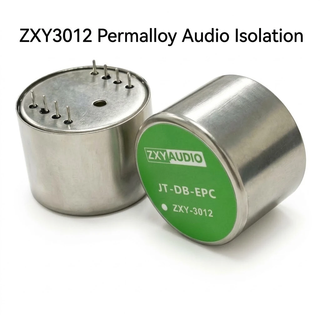
ZXY-3012 Permalloy Audio Isolation Transformer, DIP Through-Hole, Sealed 31.0 mm Metal Case, Five Turns Ratios from 1:1 to 12:1
A permalloy isolation transformer in a sealed metal can, offered in five turns ratios that share one pin base. The core is a high permeability nickel iron alloy, and that is the whole argument for the part: permeability buys low frequency response from a small can, so 20 Hz arrives intact from something 22.0 mm high. The same property caps the level, because a permalloy core saturates early, which is why every ratio is sold with a maximum 20 Hz input at one percent distortion instead of a power figure. Two windings, no d.c. path between them, and a metal case that screens by itself.
- Permalloy, high permeability nickel iron core, with a 20 Hz to 20 kHz passband on every variant.
- Sealed cylindrical metal case, 31.0 mm diameter and 22.0 mm body height.
- Five turns ratios, 1:1, 1.5:1, 3.5:1, 8:1 and 12:1, all within plus or minus 2 percent.
- Response within plus or minus 0.03 dB at 12:1, no worse than plus or minus 0.25 dB across the set.
- Maximum 20 Hz input at 1 percent distortion from +2 dBu to +21.5 dBu, by variant.
- Hi-pot 1250 V at 1 mA for 60 s; DIP pins on 3.8 mm pitch and 19.0 mm row spacing.
1. Product Name
ZXY-3012 is the product marking. JT-DB-EPC is the drawing model designation printed above it on the case label, and ZXYAUDIO and ZXYL are the two brand marks used across the images and the specification sheet. The part is a permalloy audio isolation transformer in a sealed cylindrical metal case, 31.0 mm across and 22.0 mm high, with six through-hole pins on the underside in two rows and no fixing flange. It is mounted by its pins into a board or a socket.
The label is the only place the part states its own specification, so it is worth reading closely. It carries the brand, the word TRANSFORMERS, the drawing model JT-DB-EPC, the marking ZXY-3012, and around the rim the line Freq. Response: 20Hz - 20kHz and Ratio: 1.1 - 12:1. Note the punctuation in that last figure: the same line uses a full stop in 1.1 and a colon in 12:1, and every other document gives the range as starting at 1:1. The range is read here as 1:1 to 12:1, and the label as printed is noted rather than tidied.
2. What It Does
The job is the same one every isolation transformer does: two pieces of equipment share a mains earth, the shield of the cable between them closes a loop, and the current in that loop arrives across the signal as hum at the mains frequency and its harmonics. A transformer in the path breaks the loop, because the signal crosses by induction and the copper does not touch. As a side effect it also blocks d.c., which is why a part like this protects the stage behind it from an offset fault or from phantom power being applied across an output, and why the description lists that as a feature rather than a claim.
The permalloy core is what makes the shape possible. Permeability sets how much inductance a given number of turns produces, and inductance is what keeps the primary from shorting the signal at low frequency, so a high permeability alloy reaches 20 Hz with fewer turns and a smaller core than silicon steel would need. The price is saturation: nickel iron alloys run out of flux earlier than steel, which is why this part is specified by a maximum input level at 20 Hz and one percent distortion rather than by a power rating. It is a line level component and the table should be read that way.
3. The Five Ratios
This is the part of the product that has to be chosen before anything else. Five windings occupy the same case and the same six pins, and what changes between them is the ratio, the DC resistance of each winding, the level the core will take at 20 Hz, and how flat the response is. A higher step-down ratio puts more turns on the primary, which raises its resistance and raises the voltage it can accept before the core saturates, so the level column improves from one end of the table to the other while the primary resistance climbs with it.
| Turns ratio | DCR pins 1-4, max | DCR pins 5-8, max | Max 20 Hz input, 1 percent THD | Response, 20 Hz to 20 kHz | Hi-pot |
|---|---|---|---|---|---|
| 1:1 | 1.9 kohm | 2.3 kohm | +19 dBu | plus or minus 0.06 dB | 1250 V |
| 1.5:1 | 42 ohm | 15 ohm | +2 dBu | plus or minus 0.25 dB | 1250 V |
| 3.5:1 | 257 ohm | 26 ohm | +4 dBu | plus or minus 0.17 dB | 1250 V |
| 8:1 | 1.87 kohm | 80 ohm | +21 dBu | plus or minus 0.25 dB | 1250 V |
| 12:1 | 3.8 kohm | 62 ohm | +21.5 dBu | plus or minus 0.03 dB | 1250 V |
The levels deserve translating, because decibels hide how different the variants are. The 1.5:1 build takes +2 dBu at 20 Hz, which is about 0.98 Vrms: that is a low level part and it will not survive a hot line output at the bottom of the band. The 12:1 build takes +21.5 dBu, about 9.2 Vrms, which is a different class of headroom altogether. Both conversions are arithmetic on the dBu definition and both are quoted here as derived.
The set is not a doubling series either. The ratios are 1:1, 1.5:1, 3.5:1, 8:1 and 12:1, which square to impedance steps of 1, 2.25, 12.25, 64 and 144, so they are not the 2 and 4 and 8 of a catalogue ladder. They read as ratios cut to match particular equipment rather than as a standard range, which is worth asking about: the answer usually tells you what each build was originally designed into.
4. Core, Case and Terminals
The case is a drawn metal can with a green printed label bonded to the face, and a rolled rim at the base where the can meets the header. Because the can is metal and sealed, the electrostatic screen is the enclosure: there is no separate shield pin and none is needed, provided the can is bonded to the chassis or to the reference the layout wants. That is the practical difference between this part and a moulded-case transformer with a shield terminal, and it is why the mounting surface matters as much as the winding.
Six pins leave the base in two rows, numbered 1 and 4 on one side and 8, 6, 7 and 5 on the other, on a 3.8 mm pitch within a row and 19.0 mm between rows. That row spacing is wider than any standard dual-in-line grid, so the part needs its own footprint or a socket made for it rather than a generic DIP position. There is also a plain hole in the centre of the base, drawn but never dimensioned or named; on a sealed can of this kind it is normally a fill or vent hole from potting, and it should not be used as a locating feature without confirmation.
5. Electrical Specification
Everything electrical in this product is quoted at 25 degrees C on a controlled specification sheet, which is a better starting point than most parts in the class offer. The conditions are uniform: the same 20 Hz to 20 kHz band, the same 1250 V dielectric test with a 1 mA leakage limit held for a minute, the same 2 percent tolerance on turns ratio. What is not uniform is the response and the level, both of which move with the ratio, so they belong in the ratio table rather than in a single specification line.
| Parameter | Value | Applies to |
|---|---|---|
| Turns ratio | 1:1, 1.5:1, 3.5:1, 8:1, 12:1, plus or minus 2 percent | Every variant |
| Frequency range | 20 Hz to 20 kHz | Every variant |
| Dielectric withstand | 1250 V, 1 mA leakage limit, 60 s | Every variant |
| Reference temperature | 25 degrees C | Every published figure |
| Core material | Permalloy | Nickel iron, high permeability |
| Case | Sealed metal, 31.0 mm diameter by 22.0 mm | Cylindrical |
| Package | DIP, through-hole | Six pins on the base |
| Nominal impedance | Not stated | No impedance for any ratio |
| Insertion loss | Not stated | Not published |
| Operating temperature | Not stated | Only the 25 degrees C reference is given |
| Weight | Not stated | Not published |
6. Mechanical Dimensions
The outline is simple and the drawing covers it: a cylinder with a diameter, a height and a pin field. There is no flange, no bracket and no threaded insert, so the mechanical interface is entirely the six pins plus whatever the board or the socket provides. For a part that weighs what a 31.0 mm metal can weighs, that is worth thinking about before the footprint is committed, because the pins carry both the signal and the mass.
| Dimension | Value | Where it is drawn |
|---|---|---|
| Case diameter | 31.0 mm | Outline and specification sheet |
| Body height | 22.0 mm | Outline and specification sheet |
| Pin pitch, within a row | 3.8 mm | Bottom view |
| Pin row spacing | 19.0 mm plus or minus 0.5 mm | Bottom view |
| Pin length | 5.0 mm, printed with e.g. | Front view |
| Pins drawn | 1, 4, 8, 6, 7 and 5 | Bottom view, six pins in two rows |
| Pins assigned | 1, 4, 8 and 5 | Schematic |
| Centre hole | Drawn, not dimensioned | Bottom view |
| Mounting | Through-hole, no fixing flange | All views |
| Weight | Not stated | Not published |
7. Application
The obvious homes are line level: a console output into a house system, a balanced to unbalanced interface, a microphone preamplifier input, a rack to rack tie line that hums. The 1:1 build is the one for those, because isolation is the whole requirement and the level should not move. The stepped builds answer a different question, matching a high impedance source down to a low impedance input, which is the classic direct box problem and also the reason a 12:1 part can take a speaker level or a hot instrument signal at 20 Hz that would saturate a 1.5:1 part.
Beyond audio equipment the description names voice and data coupling for telephones, fax, IP voice terminals and modems, which is the same transformer doing a different job: a galvanic barrier between a line and a terminal that must not share its ground, at voice band rather than full audio band. Car audio and installed PA are the other two named uses, both for the same reason, breaking a ground loop between a head unit and an amplifier or between racks in a building.
The through-hole package is worth noting for its own sake. It is a part you can fit and replace by hand, which matters in installed systems and in equipment that is serviced rather than scrapped. The second scene shows it standing on a board next to the tweezers and iron it was fitted with, which is the honest picture of how this package gets used.
8. Ordering and Marking
Order by model and ratio together. The model fixes the case, the core, the pins and the dielectric test; the ratio fixes the winding, the resistance, the maximum 20 Hz level and the response. Because one panel ties the model number to 12:1 while another ties it to 1:1 and the label describes a range, the ratio must appear on the purchase order as an independent item. Customised designs and factory direct supply are offered on request, which is the route for a ratio or a pin arrangement that is not in the table.
The four marks are shown together on one panel, below the transformer rather than on the case label, and no certificate number appears anywhere in the material. That is normal for a product shot and it is not evidence either way; what it means is that the marks should be confirmed against the current certificates before they are relied on in a submission, and the numbers requested with the sample.
| Item | Status | Why it matters here |
|---|---|---|
| Which ratio ships | Label says a range, panels say 12:1 and 1:1 | Ratio decides the level limit and the impedance; a price is meaningless without it |
| Outline drawing | Carries template placeholder text | It asks the reader to pick a ratio and gives the pin length as an example |
| Pin 2 | Drawn on one schematic as 2 percent, absent from the other | Reads like a centre tap, but could be the tolerance label placed on the pin row |
| Pins 6 and 7 | Drawn, never assigned | Two of six terminals have no defined function |
| Nominal impedance | Not published | The one number an audio match is normally bought on |
| Insertion loss | Not published | Decides whether the part can sit in a chain without a gain change |
| Operating temperature | Not published | Only the 25 degrees C reference exists |
| Certificate numbers | None printed | Four marks, no file numbers behind them |
| Price, MOQ, packing, lead time | Not in this material | Commercial terms are quoted separately |