loading

ZXY: 26 Years of Excellence as a Leading Transformer and Inductor Manufacturer ・ One-Stop Solutions

ZXY-3529 Permalloy Audio Isolation Transformer, 1+1:1 / 4:1 Turns Ratio, 10 Hz-40 kHz, Hi-POT 1250 V, 8-Pin DIP, 35.0 x 29.0 x 26.0 mm 1
ZXY-3529 Permalloy Audio Isolation Transformer, 1+1:1 / 4:1 Turns Ratio, 10 Hz-40 kHz, Hi-POT 1250 V, 8-Pin DIP, 35.0 x 29.0 x 26.0 mm 2
ZXY-3529 Permalloy Audio Isolation Transformer, 1+1:1 / 4:1 Turns Ratio, 10 Hz-40 kHz, Hi-POT 1250 V, 8-Pin DIP, 35.0 x 29.0 x 26.0 mm 3
ZXY-3529 Permalloy Audio Isolation Transformer, 1+1:1 / 4:1 Turns Ratio, 10 Hz-40 kHz, Hi-POT 1250 V, 8-Pin DIP, 35.0 x 29.0 x 26.0 mm 4
ZXY-3529 Permalloy Audio Isolation Transformer, 1+1:1 / 4:1 Turns Ratio, 10 Hz-40 kHz, Hi-POT 1250 V, 8-Pin DIP, 35.0 x 29.0 x 26.0 mm 5
ZXY-3529 Permalloy Audio Isolation Transformer, 1+1:1 / 4:1 Turns Ratio, 10 Hz-40 kHz, Hi-POT 1250 V, 8-Pin DIP, 35.0 x 29.0 x 26.0 mm 6
ZXY-3529 Permalloy Audio Isolation Transformer, 1+1:1 / 4:1 Turns Ratio, 10 Hz-40 kHz, Hi-POT 1250 V, 8-Pin DIP, 35.0 x 29.0 x 26.0 mm 7
ZXY-3529 Permalloy Audio Isolation Transformer, 1+1:1 / 4:1 Turns Ratio, 10 Hz-40 kHz, Hi-POT 1250 V, 8-Pin DIP, 35.0 x 29.0 x 26.0 mm 8
ZXY-3529 Permalloy Audio Isolation Transformer, 1+1:1 / 4:1 Turns Ratio, 10 Hz-40 kHz, Hi-POT 1250 V, 8-Pin DIP, 35.0 x 29.0 x 26.0 mm 9
ZXY-3529 Permalloy Audio Isolation Transformer, 1+1:1 / 4:1 Turns Ratio, 10 Hz-40 kHz, Hi-POT 1250 V, 8-Pin DIP, 35.0 x 29.0 x 26.0 mm 10
ZXY-3529 Permalloy Audio Isolation Transformer, 1+1:1 / 4:1 Turns Ratio, 10 Hz-40 kHz, Hi-POT 1250 V, 8-Pin DIP, 35.0 x 29.0 x 26.0 mm 1
ZXY-3529 Permalloy Audio Isolation Transformer, 1+1:1 / 4:1 Turns Ratio, 10 Hz-40 kHz, Hi-POT 1250 V, 8-Pin DIP, 35.0 x 29.0 x 26.0 mm 2
ZXY-3529 Permalloy Audio Isolation Transformer, 1+1:1 / 4:1 Turns Ratio, 10 Hz-40 kHz, Hi-POT 1250 V, 8-Pin DIP, 35.0 x 29.0 x 26.0 mm 3
ZXY-3529 Permalloy Audio Isolation Transformer, 1+1:1 / 4:1 Turns Ratio, 10 Hz-40 kHz, Hi-POT 1250 V, 8-Pin DIP, 35.0 x 29.0 x 26.0 mm 4
ZXY-3529 Permalloy Audio Isolation Transformer, 1+1:1 / 4:1 Turns Ratio, 10 Hz-40 kHz, Hi-POT 1250 V, 8-Pin DIP, 35.0 x 29.0 x 26.0 mm 5
ZXY-3529 Permalloy Audio Isolation Transformer, 1+1:1 / 4:1 Turns Ratio, 10 Hz-40 kHz, Hi-POT 1250 V, 8-Pin DIP, 35.0 x 29.0 x 26.0 mm 6
ZXY-3529 Permalloy Audio Isolation Transformer, 1+1:1 / 4:1 Turns Ratio, 10 Hz-40 kHz, Hi-POT 1250 V, 8-Pin DIP, 35.0 x 29.0 x 26.0 mm 7
ZXY-3529 Permalloy Audio Isolation Transformer, 1+1:1 / 4:1 Turns Ratio, 10 Hz-40 kHz, Hi-POT 1250 V, 8-Pin DIP, 35.0 x 29.0 x 26.0 mm 8
ZXY-3529 Permalloy Audio Isolation Transformer, 1+1:1 / 4:1 Turns Ratio, 10 Hz-40 kHz, Hi-POT 1250 V, 8-Pin DIP, 35.0 x 29.0 x 26.0 mm 9
ZXY-3529 Permalloy Audio Isolation Transformer, 1+1:1 / 4:1 Turns Ratio, 10 Hz-40 kHz, Hi-POT 1250 V, 8-Pin DIP, 35.0 x 29.0 x 26.0 mm 10

ZXY-3529 Permalloy Audio Isolation Transformer, 1+1:1 / 4:1 Turns Ratio, 10 Hz-40 kHz, Hi-POT 1250 V, 8-Pin DIP, 35.0 x 29.0 x 26.0 mm

Permalloy isolation transformer | 1+1:1 and 4:1 | 10 Hz-40 kHz | 8-pin DIP, Hi-POT 1250 V

ZXY-3529 is a permalloy audio isolation transformer in an 8-pin DIP through-hole case measuring 35.0 × 29.0 × 26.0 mm. Two variants share the footprint: 1+1:1 at DCR 26 + 52 Ω max and +12 dBu input, and 4:1 at 700 Ω max and +22 dBu. Frequency range 10 Hz to 40 kHz, response within ±0.16 dB / ±0.10 dB from 20 Hz to 20 kHz, Hi-POT 1250 V.

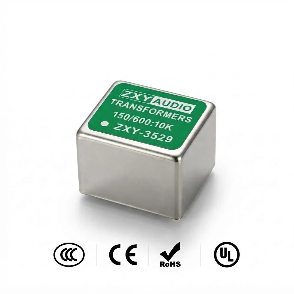
ZXY-3529 in the permalloy case, nameplate 150/600:10K
KEY HIGHLIGHTS
  • Turns ratio 1+1:1 or 4:1 on one part number, one 35.0 x 29.0 x 26.0 mm case
  • Frequency range 10 Hz - 40 kHz; 20 Hz - 20 kHz within 0.16 dB (1+1:1), 0.10 dB (4:1)
  • Maximum 50 Hz input at 1% THD +12 dBu (1+1:1) and +22 dBu (4:1)
  • DCR 26 + 52 ohm max on the 1-4 side, 70 ohm max on the 5-8 side, both at 25 C
  • Hi-POT 1250 V, 1 mA, 60 s; permalloy case; 8-pin DIP on a 5.0 mm pitch
Two designations appear on this part and both are correct. The nameplate reads 150/600:10K, which is an impedance designation for the primary taps and the secondary. The specification table gives turns ratios 1+1:1 and 4:1 for the two windings offered on this model. Impedance and turns ratio are not the same number: impedance scales with the square of the turns ratio, so a 600 Ω to 10 kΩ pairing is a 1:4 turns ratio of about 1:4. Confirm which variant your circuit needs before ordering.
5.0
Model:
ZXY-3529
Frequency Range:
10 Hz - 40 kHz
Case:
Permalloy case, rounded corners
Hi-POT:
1250 V, 1 mA, 60 s
Input Level:
+12 dBu (1+1
Frequency Response:
20 Hz - 20 kHz, ±0.16 dB (1+1
Package:
8-pin DIP through-hole, two rows of 4
Dimensions:
35.0 × 29.0 × 26.0 mm
Turns Ratio:
1+1
Product Type:
Permalloy audio isolation transformer
design customization

    oops...!

    no product data.

    Go to homepage
    Case Terminal
    Pin 6
    Core Terminal
    Pin 7
    Terminal Rows
    Two rows of 4, markings 5-8 and 4-1
    Hi-POT
    1250 V, 1 mA, 60 s
    THD Reference
    1% at 50 Hz
    Input Level
    +12 dBu (1+1
    DCR Secondary
    70 Ω max (1+1
    DCR Primary
    26 + 52 Ω max (1+1
    Case Finish
    Rounded corners, screened body
    Case Material
    Permalloy, high-permeability nickel-iron
    Nameplate
    150/600
    Package
    8-pin DIP through-hole
    Model
    ZXY-3529
    Dimensions
    35.0 × 29.0 × 26.0 mm
    Frequency Range
    10 Hz - 40 kHz
    Product Type
    Permalloy audio isolation transformer
    Compliance
    CCC / CE / RoHS / UL
    Pin Pitch
    5.0 mm
    Frequency Response
    20 Hz - 20 kHz, ±0.16 dB (1+1
    Turns Ratio
    1+1

    1. Product Name

    ZXY-3529 permalloy audio isolation transformer. 8-pin DIP through-hole package, turns ratio 1+1:1 or 4:1, frequency range 10 Hz to 40 kHz, Hi-POT 1250 V at 1 mA for 60 s, case 35.0 x 29.0 x 26.0 mm, pin pitch 5.0 mm, nameplate 150/600:10K.

    The same part from four angles: nameplate face, both terminal rows and one plain side
    The same part from four angles: nameplate face, both terminal rows and one plain side
    Single part, front face
    Single part, front face

    Overview. A single part carries the whole isolation function: a permalloy can, a winding arrangement brought out to eight DIP terminals, and a nameplate that states the impedance designation and the model. Nothing else is needed on the board apart from the land pattern.

    Two variants are specified on the same model number. They share the case, the land pattern and the pin assignments, and differ in winding: the 1+1:1 version for line-level coupling, the 4:1 version for higher input levels. The table in chapter 5 lists both columns side by side so the difference is visible without cross-referencing two documents.

    2. Feature

    Two turns-ratio variants on one part number. 1+1:1 for line-level coupling and 4:1 for higher input levels, both in the same 35.0 × 29.0 × 26.0 mm case.

    Permalloy case. a high-permeability nickel-iron case with rounded corners, so the magnetic circuit is closed inside the can and the part is screened from nearby fields without a separate shield.

    10 Hz to 40 kHz working range. the overall band; the ±0.16 dB / ±0.10 dB tolerance is specified from 20 Hz to 20 kHz, referred to +4 dBu at 1 kHz.

    Input level to +22 dBu. maximum 50 Hz input at 1% THD, +12 dBu on the 1+1:1 variant.

    DCR 26 + 52 Ω max. on the 1-4 side of the 1+1:1 variant, 70 Ω max on the 5-8 side, both at 25 °C.

    Hi-POT 1250 V. 1 mA leakage limit for 60 s between winding and case.

    8-pin DIP through-hole terminals. two rows of four on a 5.0 mm pitch, marked 5 6 7 8 on one row and 4 3 2 1 on the other, so the part is placed and soldered like any other DIP device.

    Separate core and case terminals. pins 7 and 6 bring the internal core and the case out to the board when the design needs them bonded.

    Orientation dot on the nameplate. with ZXY AUDIO TRANSFORMERS / 150/600:10K / ZXY-3529 laser marked.

    Customized designs available. factory-direct supply from stock, with custom windings on request.

    8-pin DIP through-hole terminals and the permalloy housing
    8-pin DIP through-hole terminals and the permalloy housing

    The case is the shield. There is no separate can, bracket or mu-metal wrapper to add at assembly: the permalloy body closes the magnetic path around the winding and the only thing the board has to provide is the eight holes and, where the design calls for it, a bond to pins 6 and 7.

    3. Advantage

    Protects the stage in front of it. the transformer decouples input from output, so a fault downstream cannot burn out the output stage driving the line.

    Removes grounding hum. where two pieces of equipment are earthed at different points, the isolation is what takes the AC hum out that a direct connection would carry.

    Balanced and unbalanced transmission. the same part reduces external interference in either arrangement, and couples voice or data between circuits that must not share a reference.

    One footprint, two ratios. a design that moves from 1+1:1 to 4:1 keeps the same PCB land pattern, the same outline and the same panel cutout.

    DIP terminals. through-hole mounting means straightforward replacement in the field and no reflow profile to re-qualify.

    Tight response across the audio band. ±0.16 dB (1+1:1) and ±0.10 dB (4:1) from 20 Hz to 20 kHz, so the part does not colour the signal it passes.

    Two parts, nameplate side up
    Two parts, nameplate side up
    Terminal side up, two rows of four pins on a 5.0 mm pitch
    Terminal side up, two rows of four pins on a 5.0 mm pitch

    Because both ratios sit in the same case, a design that moves from 1+1:1 to 4:1 keeps its PCB land pattern, its panel cutout and its assembly drawing. That is worth more than it sounds in a product that is often specified late in a project, after the board has already been laid out.

    4. Application

    Hi-Fi audio systems. between a source and a preamplifier or power amplifier where hum and ground loops are audible.

    Home theater. isolating a processor output from a power amplifier input across a long cable run.

    Car audio. breaking the ground path between a head unit and an external amplifier.

    Mixing console signal isolation output. taking a console output to a recorder, a broadcast line or a stage feed without tying the grounds together.

    Multi-channel isolated signal output. one part per channel where several outputs leave the same chassis.

    Mounted on a board: the case sits above the copper so the winding stays clear of the track
    Mounted on a board: the case sits above the copper so the winding stays clear of the track

    The common thread across these uses is a ground that cannot be shared. Once two chassis sit on different earth potentials, a direct connection carries the difference as hum; the transformer passes the signal and not the difference, which is the entire job.

    5. Application Specifications

    Electrical data at 25 degrees C, as declared on the ZXY-3529 specification sheet.

    5.1 Electrical specification

    Parameter1+1:14:1
    Turns ratio1+1:14:1
    DCR (1-4) / Ω max at 25 °C26 + 52700
    DCR (5-8) / Ω max at 25 °C7045
    Maximum 50 Hz input level, 1% THD+12 dBu+22 dBu
    Freq. response, ref. +4 dBu at 1 kHz20 Hz - 20 kHz = ±0.16 dB20 Hz - 20 kHz = ±0.10 dB
    Hi-POT, 1 mA, 60 s1250 V1250 V

    Overall frequency range is 10 Hz to 40 kHz; the ±0.16 dB and ±0.10 dB tolerances in the table are specified from 20 Hz to 20 kHz, referred to +4 dBu at 1 kHz. Hi-POT is 1250 V with a 1 mA leakage limit held for 60 s.

    Winding arrangement: 150 Ω / 600 Ω primary against a 10 kΩ secondary
    Winding arrangement: 150 Ω / 600 Ω primary against a 10 kΩ secondary

    5.2 Construction and mechanical data

    ItemValue
    CasePermalloy (high-permeability nickel-iron) case with rounded corners
    Package8-pin DIP through-hole, two rows of 4 terminals
    Terminal-side marking5 6 7 8 on one row, 4 3 2 1 on the opposite row
    Pin pitch5.0 mm
    Case dimensions35.0 mm (W) × 29.0 mm (D) × 26.0 mm (H), case body only, terminals excluded
    Winding arrangementWindings between pins 1-3 and pins 2-4 (DCR 1-4); winding between pins 5-8 (DCR 5-8); pins 7 (core) and 6 (can) are the internal core and case terminals
    Envelope 35.0 × 29.0 × 26.0 mm with the winding arrangement drawn alongside
    Envelope 35.0 × 29.0 × 26.0 mm with the winding arrangement drawn alongside
    Outline drawing, unit mm: 35.0 wide, 26.0 body height, 29.0 deep, 5.0 mm pin pitch
    Outline drawing, unit mm: 35.0 wide, 26.0 body height, 29.0 deep, 5.0 mm pin pitch

    5.3 Winding and pin assignment

    TerminalFunction
    Pins 1 - 3Primary winding, first section (measured as DCR 1-4 together with pins 2 - 4)
    Pins 2 - 4Primary winding, second section
    Pins 5 - 8Secondary winding (DCR 5-8)
    Pin 7Core terminal
    Pin 6Case (can) terminal
    Pins 7 and 6 are the core and the case, not signal terminals. They are brought out so a design can bond the core and the can to a chosen potential; leave them unconnected and the transformer still works, bond them and the shielding is tied to the board reference. The dimension drawing above carries a second 6 (can) label hanging below the schematic; the attached callout is the correct one, and 7 is the core terminal as tabulated.
    Two designations appear on this part and both are correct. The nameplate reads 150/600:10K, which is an impedance designation for the primary taps and the secondary. The specification table gives turns ratios 1+1:1 and 4:1 for the two windings offered on this model. Impedance and turns ratio are not the same number: impedance scales with the square of the turns ratio, so a 600 Ω to 10 kΩ pairing is a 1:4 turns ratio of about 1:4. Confirm which variant your circuit needs before ordering.

    6. Quality & Testing Assurance

    Each parameter below is specified at 25 degrees C on the manufacturer specification sheet, and the part is marked CCC, CE, RoHS and UL.

    TestDeclared value
    Dielectric withstand (Hi-POT)1250 V, 1 mA, 60 s
    Turns ratio1+1:1 and 4:1, as tabulated
    DC resistance at 25 °C26 + 52 Ω / 70 Ω max for 1+1:1; 700 Ω / 45 Ω max for 4:1
    Maximum 50 Hz input at 1% THD+12 dBu (1+1:1) and +22 dBu (4:1)
    Frequency response, ref. +4 dBu at 1 kHz20 Hz - 20 kHz within ±0.16 dB (1+1:1) and ±0.10 dB (4:1)
    Test ambientAll electrical parameters specified at 25 °C
    The compliance marks appear on the product image supplied with this listing. No certificate numbers or issuing bodies were supplied, so confirm the certificate numbers and the scope of each mark before publishing a certification claim.

    Brand / manufacturer: ZXY, Shenzhen Zhixiangyuan Electronics Co., Ltd. http://www.zxycoil.com

    Message Form
    We Can Help You Solve Any Problem 
    Just leave your email or phone number in the contact form so we can send you a free quote for our wide range of designs!
    Related Products
    Huizhou Company Address
    Zhixiangyuan Technology Co., Ltd., 5th Floor, Building 4, Xinghe Industrial Park, Zhongkai High tech Zone, Huicheng District, Huizhou City, Guangdong Province
    Contact Us
    Contact Person: Rhea Chen
    Tel/WhatsApp: +86 13554723725
    Fax: 86-0755-23779620
    Shenzhen Company Address
    Room 202, Yingfei Haocheng Science and Technology Park, Guansheng 5th Road, Luhu Community, Guanhu Street, Longhua District, Shenzhen City, Guangdong Province, China
    Customer service
    detect