
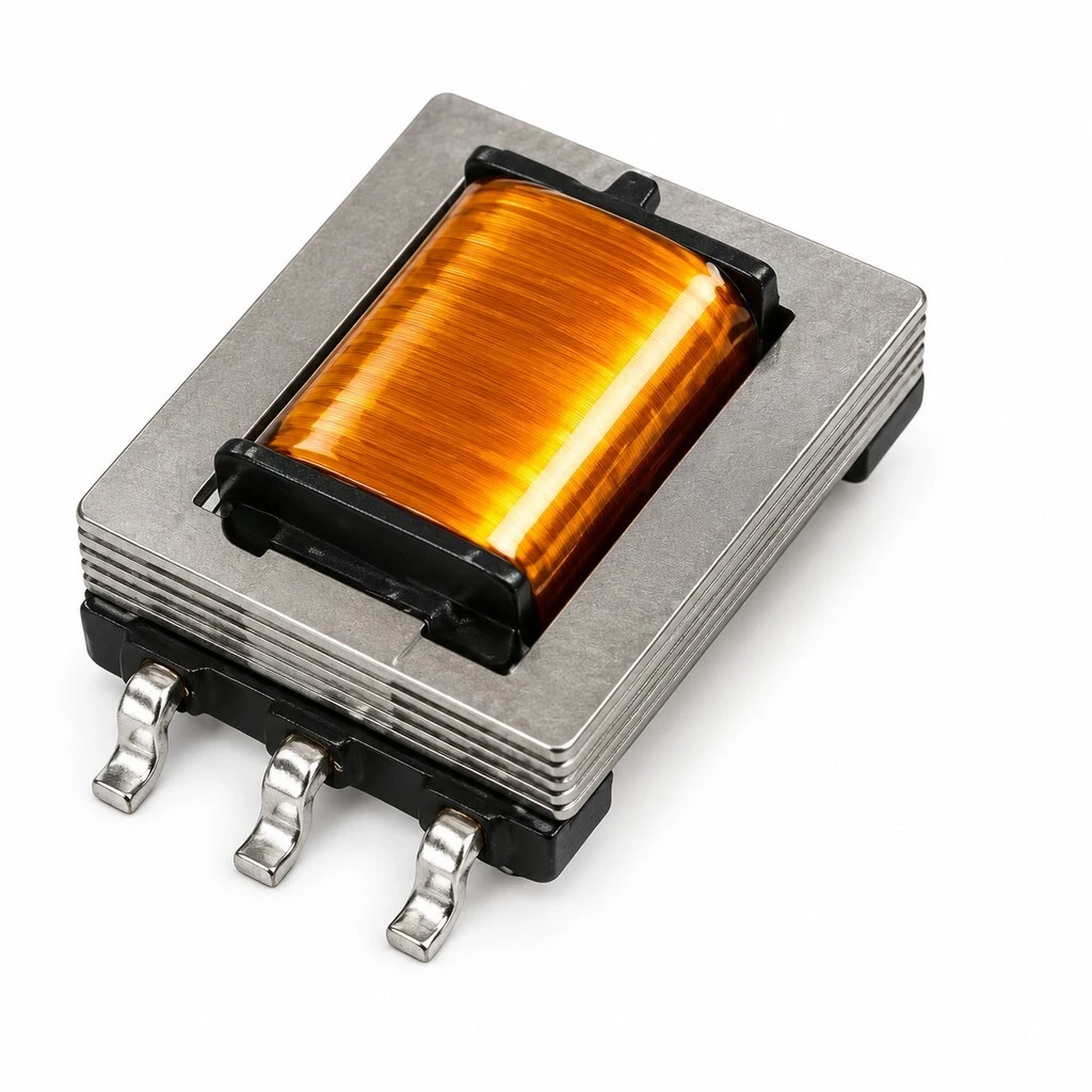
SMD Audio Isolation Transformer, ED8-600 Ohm to 600 Ohm, 1:1, 6-Pin Surface Mount, 10.5 mm, 1250 V AC Hi-Pot
This is the part that goes between two pieces of audio equipment when the shield between them is carrying current. A 1:1 winding at 600 ohm passes the signal at the level it arrived and breaks the ground path, so the loop that produced the hum is no longer closed. The same winding makes the two sides see the same impedance, which is why the part is used on line outputs, transformer-balanced outputs and inputs that have to survive a long cable. It is a signal component: 1250 V AC of isolation is enough to break a ground loop and to keep a fault off a connector, and it is not a mains barrier.
- 600 ohm to 600 ohm at 1:1, 2 percent tolerance: a line level part, not a power transformer.
- Six gull-wing pins, 10.5 mm long, 4.7 mm body height, 8.5 mm callout beside the pins.
- Inductance 2.0 H or more at 250 Hz and 0.5 V; DC resistance 66 ohm and 81 ohm at 15 percent.
- Hi-pot 1250 V AC at 1 mA for 2 seconds between the windings.
- Laminated high permeability core, multi-layer enamelled copper wire, amber thermal wrap.
- Tape and reel quoted, but no reel quantity, pocket pitch, pinout or land pattern is published.
1. Product Name
A 600 ohm to 600 ohm audio isolation transformer in a surface mount package. The two windings are 1:1, so the part is a galvanic break in a line level path rather than a matching transformer: the voltage across it stays where it was, and only the ground connection between the two sides disappears. Six gull-wing pins, three to each side, put it on the board like any other SMD part, which is the reason it exists next to the cased parts it replaces.
No model or part number appears on any of the ten panels, including the two that carry a headline and the one that shows the specification box. The part is therefore identified by its electrical description, 600 ohm to 600 ohm at 1:1 in a 6-pin SMD package, and by its dimensions. If you need a code for a bill of materials, ask the supplier what they use; this page does not invent one.
2. What It Does
Two earthed pieces of equipment on the same mains produce a loop through their shields, and the current in that loop appears across the signal as hum at the mains frequency and its harmonics. A transformer in the path removes the loop, because there is no conductive connection left between the two grounds. A 1:1 turns ratio is used where the level must not change: the part is inserted in series with the signal, and the receiving stage sees the same impedance it saw before. The same arrangement also breaks the path that digital hash uses to travel between a converter and an amplifier on a shared ground.
3. Construction
The core is a laminated stack of high permeability material, visible as the silver plates above and below the coil, and the two windings sit on a moulded bobbin between the core halves. The coil is wound multi-layer in enamelled copper wire, and the whole winding is wrapped in a high gloss amber thermal film that is the most visible feature of the part. The pins are gull-wing, formed from the lead frame and tinned, and they exit the moulding on the two long sides so the part sits flat on the board.
4. Dimensions and Footprint
One view is dimensioned and it is the long side. The body is 10.5 mm long and 4.7 mm high, both marked maximum, and the third callout reads 8.5 mm maximum, drawn beside the pin ends in the same view but not named. What the drawing does not give is the depth, which is the dimension a land pattern actually needs, and it does not give a pin pitch, a pad size or a pin numbering. The footprint line under the drawing says only 6-pin SMD horizontal.
5. Electrical Specifications
The specification box is the whole electrical offer, and it is short. Impedance is quoted as 600 ohm to 600 ohm at 1:1 with a 2 percent tolerance, inductance as 2.0 H or more at 250 Hz and 0.5 V, DC resistance as 66 ohm and 81 ohm at plus or minus 15 percent, and the hi-pot as 1250 V AC at 1 mA for 2 seconds. The header fixes the test temperature at 25 degrees C and nothing else: there is no frequency response, no insertion loss, no rated level, no total harmonic distortion figure in the specification itself, no insulation resistance and no operating temperature range.
5.1 The published set
| Parameter | Value | Note |
|---|---|---|
| Impedance | 600 ohm : 600 ohm, 1:1, 2 percent | The ratio is set by the impedance match |
| Inductance | 2.0 H or more | Measured at 250 Hz, 0.5 V |
| DC resistance | 66 ohm and 81 ohm, 15 percent | Which winding is which is not stated |
| Hi-pot | 1250 V AC, 1 mA, 2 s | Winding to winding |
| Test temperature | 25 degrees C | The only condition given |
| Frequency response | Not stated | Wide response is claimed, no curve shown |
| Rated level | Not stated | No power, voltage or dBm rating published |
| Insulation resistance | Not stated | Not published |
6. Measured on the Bench
One photograph shows the part connected to a digital audio analyzer through a probe lead, with the instrument reading 0.00023 percent THD+N at 1.000 kHz, a level of -7.10 dBFS and a SINAD of 112.5 dB. That is a bench observation of one unit in one setup, not a guaranteed figure: the drive level, the source impedance, the load and the bandwidth of the measurement are all outside the frame, and the specification box above does not repeat any of these numbers.
7. Supply Format
The supply format is quoted as tape and reel for SMT bulk assembly, and three units are shown side by side to make the point. No reel, tape, pocket or cover tape appears in the photographs, and no reel quantity, pocket pitch, tape width or orientation is stated. The three units in the picture look alike in length and differ slightly in apparent height, which is most likely the camera angle rather than a second height option, but the material does not say that either.
8. Quality and Compliance
The compliance panel carries four marks, CCC, CE, RoHS and UL Recognized, under a heading about international certifications and standards. A UL Recognized mark is a component recognition, not a listing of the finished equipment, and it does not by itself certify an end product. No certificate number, standards reference, file number or test report appears against any of the four, and the only dielectric figure anywhere in the material is the 1250 V AC hi-pot in the specification box.
| Item | Statement | Note |
|---|---|---|
| Hi-pot | 1250 V AC, 1 mA, 2 s | The only dielectric figure given |
| Insulation resistance | Not stated | Not published |
| CCC | Mark shown | No certificate number |
| CE | Mark shown | No certificate number |
| RoHS | Mark shown | No certificate number |
| UL | Recognized mark shown | Component recognition, not a listing |
9. Feature
1:1 at 600 ohm. The winding ratio is fixed by the impedance match, so the part is inserted without changing the signal level.
Six-pin SMD. Gull-wing pins on a 10.5 mm body let the part be placed and reflowed with the rest of the board.
1250 V AC isolation. Enough to break a ground loop and to hold a fault off a connector, tested at 1 mA for 2 seconds.
2.0 H of inductance. Measured at 250 Hz and 0.5 V, which is what keeps the low end of the band from loading the source.
Laminated high permeability core. A stacked core rather than a solid one, which is what a small audio part needs to reach its inductance in this size.
Amber thermal wrap. The winding is sealed under a high gloss film, which protects the fine enamelled wire during handling and reflow.
10. Advantage
It removes the loop instead of filtering it. A ground loop is a circuit problem; a transformer opens the circuit. Nothing is attenuated and nothing is added to the signal path except the part itself.
The electrical set is short but specific. Impedance with a tolerance, inductance with a test condition, both DC resistances, and a hi-pot with a current and a time. Those five numbers are what a design actually needs.
The isolation figure carries its test. 1250 V AC at 1 mA for 2 seconds is a stated test, not a marketing number.
SMD rather than cased. The same function as a cased line transformer in a part that sits inside the existing reflow process.
A measured bench figure is shown. The analyzer photograph gives 0.00023 percent THD+N at 1 kHz, which is a starting point for a conversation about a guaranteed limit.
11. Specifications
Values are transcribed from the supplier panels. Where a figure is absent the cell reads Not stated, and where the material is silent about a feature the gap is named rather than filled.
| Item | Specification | Note |
|---|---|---|
| Product | 600 ohm : 600 ohm SMD audio isolation transformer | 1:1, line level |
| Core | Laminated, high permeability | Grade not stated |
| Winding | Multi-layer enamelled copper wire | Gauge not stated |
| Pins | 6, gull-wing, surface mount | Numbering not published |
| Body | 10.5 mm long, 4.7 mm high | Both marked maximum |
| Third callout | 8.5 mm | Beside the pin ends, not named |
| Isolation | 1250 V AC, 1 mA, 2 s | Winding to winding |
| Inductance | 2.0 H or more | At 250 Hz, 0.5 V |
| DC resistance | 66 ohm and 81 ohm, 15 percent | Assignment not stated |
| Model number | None published | Not printed on any panel |
| Weight | Not stated | No figure published |
12. Application
The uses below are the ones the material points at, with a note on why a 1:1 part fits each. They describe where the part is sold, not a qualification of any one build.
Ground loop breaking. Between two earthed units on a shared supply, where the loop is audible as hum at the mains frequency.
Converter and DAC outputs. The photograph in this page shows the part on a high resolution DAC board, between the converter stage and the analog output jacks.
Balanced and unbalanced interfaces. Where a line output has to feed an input on a different ground reference without a DC path.
Digital noise isolation. Between a digital source and an analog stage, to keep converter hash off the shared ground.
Broadcast and installed audio. Long line runs between rooms or racks where the two ends are earthed separately.
Instrumentation front ends. Low level inputs that have to survive a ground difference between the sensor and the recorder.
13. Ordering
Send the application first, then the numbers. A usable enquiry says what the part sits between, gives the impedance and the turns ratio, states whether a centre tap is needed and on which winding, and quotes the pinout if the board already exists. Add the packing format, the reel quantity if the line needs one, and the quantity per order and per delivery. Because no model number is published, the description and the drawing have to carry the identity of the part.
On compliance: the panel shows CCC, CE, RoHS and UL Recognized and presents all four as covering the part. No certificate number, standards reference or report is reproduced with any of the four marks, and UL Recognized is a component recognition rather than a listing. They are reported here as marks and declarations, not as verified certifications. If your product has to meet a named standard, ask for the certificate and the report for that standard before the part is designed in.
Brand / manufacturer: ZXY, Shenzhen Zhixiangyuan Electronics Co., Ltd. http://www.zxycoil.com