
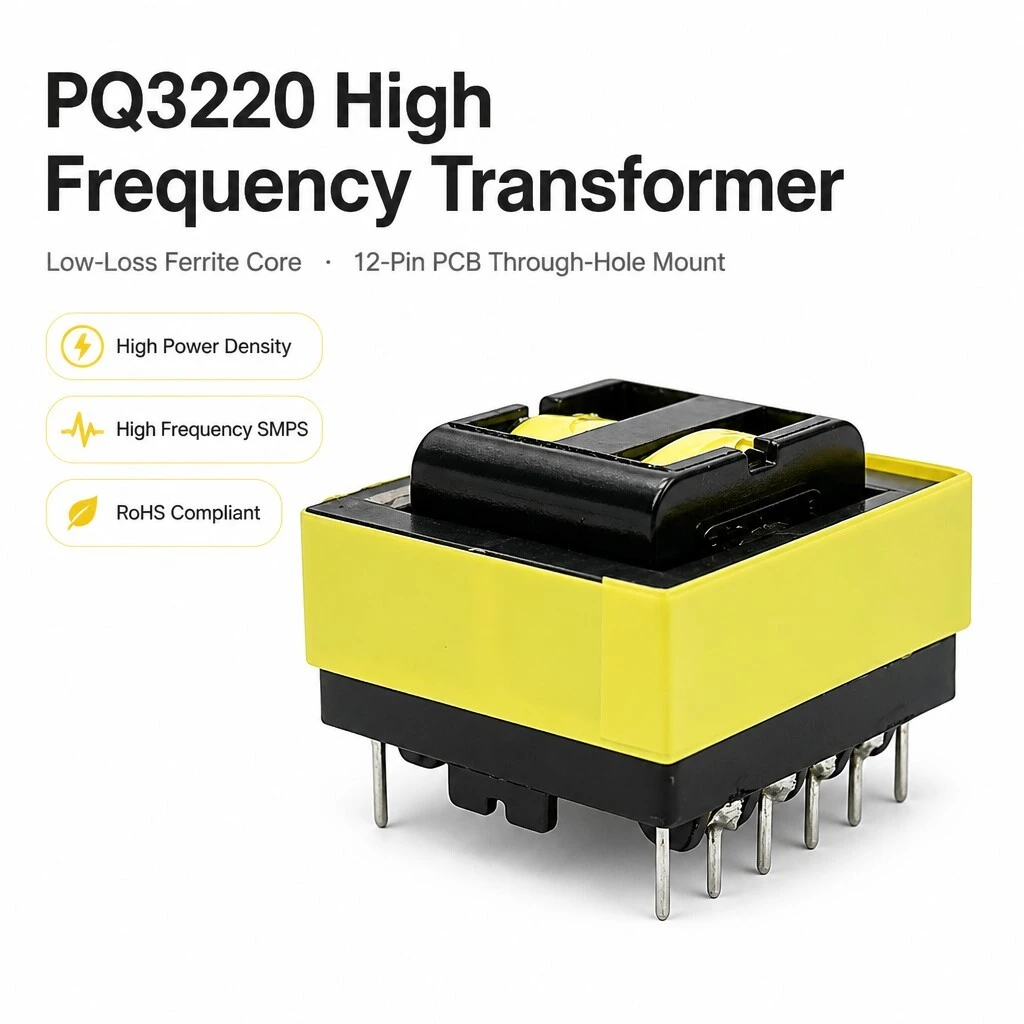
PQ3220 High Frequency Transformer, Low-Loss Ferrite Core, 12-Pin PCB Through-Hole Mount, 34.5 x 36.0 x 23.0 mm, 100-500 kHz SMPS, Custom Windings
A PQ3220 platform for switching supplies in the 100 kHz to 500 kHz band, where a potted mains part would be too slow and too large. The core is a low-loss ferrite in the PQ shape, which puts the winding window on the outside of the pot so the coil can be wound wide and short, and the twelve posts drop straight into a PCB footprint with 5.0 mm and 7.5 mm spacing. Windings are made to order, so the ratio and the inductance come from your schematic rather than from a catalogue.
- PQ3220 low-loss ferrite core, 12-pin PCB through-hole mount.
- Maximum outline 34.5 mm by 36.0 mm by 23.0 mm, pin length 3.5 +/- 0.5 mm.
- Row distance 30.5 +/- 0.5 mm, pin pitch given as 5.0 mm and 7.5 mm.
- Twelve solder posts, numbered 1 to 6 and 7 to 12, split three and three.
- Operating frequency given as 100 kHz to 500 kHz, efficiency up to 95 percent.
- Supplier declares RoHS, UL94V-0 bobbin and 3.75 kV AC high-pot on every unit.
- Windings made to order: no voltage, ratio, inductance or power rating is published.
1. Product Name
PQ3220 is the core size, not a winding. The part is a high frequency transformer built on a PQ3220 ferrite core with a twelve-post PCB termination, intended for switching supplies running between 100 kHz and 500 kHz. Because the winding is made to order, the model number fixes the core, the frame, the pinout and the envelope; the primary and secondary are then wound to the ratio and the inductance the customer's circuit needs.
That is how these parts are actually bought. A designer picks the core size from the power and the frequency, then specifies turns, wire, inductance, leakage and the pin assignment. So the useful thing to send is a winding schedule or a sample, not a voltage pair, and the useful thing to confirm first is the footprint. The dimensions and the pin numbering below are enough to lay out the board before the winding is settled.
2. Core and Construction
The core is a PQ3220 in a low-loss ferrite grade, and the material names no specific grade, so the grade is one of the items to agree at order. The PQ shape was designed for exactly this duty: the two halves are a pot with the winding window brought out to the outside face, which lets the coil be wide and short, keeps the mean turn length down and leaves a large surface for heat to leave through. The two halves clamp round the bobbin and press on the centre leg, and the assembly is held by the frame rather than by tape.
The coil sits on a black glass-filled bobbin with the winding wrapped in yellow high temperature tape, and the core is clamped through the bobbin window so both halves bear on the centre leg. The base is a moulded black block: it carries the twelve posts, the comb barriers between them and the moulded feet that stand the part off the board. The yellow tape is the outer insulation over the winding; the frame and the base are the same black moulding material.
3. Dimensions and Footprint
The maximum outline is 34.5 mm wide, 36.0 mm deep and 23.0 mm high. The pin length below the seating plane is 3.5 +/- 0.5 mm and the row distance between the two pin rows is 30.5 +/- 0.5 mm. The bottom view puts the overall span across the posts at 30.5 +/- 0.5 mm, with 7.5 +/- 0.5 mm and 5.0 +/- 0.5 mm called out under the two pin groups. The side view also carries a 0.8 +/- 0.1 mm dimension drawn against the pin.
4. Terminals and Pin Numbering
Termination is twelve solder posts in two rows of six, numbered 1 to 6 along one side and 7 to 12 along the other, each side split three and three by the centre gap. The posts stand in moulded comb barriers, which keep the copper tails apart, and the winding tails are soldered to the post roots behind those barriers. The posts are through-hole, so the part is wave or hand soldered from the underside of the board.
5. Operating Characteristics
The supplier publishes an operating band, an efficiency ceiling and three qualitative claims. No test conditions accompany any of them, so they are repeated here as the supplier states them and not as measurements.
6. Quality and Compliance
Three claims appear on the compliance panel: RoHS, a UL94V-0 flame retardant bobbin, and 100 percent high-pot and insulation testing at 3.75 kV AC. No certificate number, standard reference or report is shown with any of them.
7. Feature
PQ3220 low-loss ferrite core. The PQ shape brings the winding window to the outside face, so the coil can be wide and short and heat leaves through a large surface.
Twelve-post PCB termination. Two rows of six at 30.5 mm row distance drop straight into a through-hole footprint, with no flying leads to dress.
100 kHz to 500 kHz operating band. The frequency range the core and the wire gauge are chosen for, which is where a switching supply wants a part this size.
Yellow high temperature tape. The winding is wrapped before the core is fitted, so the outer insulation is tape rather than a potted shell.
UL94V-0 flame retardant bobbin. The bobbin and frame material is declared flame retardant to UL94V-0, which is the usual entry requirement for equipment built to a safety standard.
Wound to order. Turns, wire, inductance, leakage and pin assignment are set from the customer's schedule, so the platform covers a range of circuits.
8. Advantage
Small for the power. 34.5 mm by 36.0 mm by 23.0 mm on a platform intended for high power density, which is what makes a PQ core worth the tooling over an EI stack at these frequencies.
Fewer joints. Through-hole posts solder directly to the board, so there is no lead harness, no connector and no hand dressing on the line.
Board layout fixed early. The footprint and the pin numbering are published, so the board can be laid out before the winding is settled.
Insulation tested on every unit. The supplier declares 100 percent high-pot and insulation testing at 3.75 kV AC, which is the check that matters on a switching part.
One platform, many windings. The same core and frame carry different turns and taps, so a family of boards can share a footprint.
9. Specifications
Values are transcribed from the supplier artwork. Where it is silent the cell reads Not stated; where it contradicts itself the contradiction is named rather than resolved.
9.1 Summary
| Item | Specification | Note |
|---|---|---|
| Product | PQ3220 high frequency transformer | Platform, wound to order |
| Core | PQ3220, low-loss ferrite | Ferrite grade not stated |
| Termination | 12 pins, PCB through-hole | Two rows of six |
| Dimensions | 34.5 mm x 36.0 mm x 23.0 mm maximum | Width x depth x height |
| Pin length | 3.5 +/- 0.5 mm | Below the seating plane |
| Row distance | 30.5 +/- 0.5 mm | Between the two pin rows |
| Pin pitch | 5.0 mm / 7.5 mm | Both quoted, allocation not stated |
| Operating frequency | 100 kHz to 500 kHz | Supplier panel |
| Efficiency | Up to 95 % | Curve top, test conditions not stated |
| Dielectric strength | 3.75 kV AC | Declared as 100 % tested |
| Bobbin flammability | UL94V-0 | Declared, no certificate number |
| Winding | Custom | No voltage, ratio, inductance or power rating published |
9.2 Electrical
| Parameter | Value | Note |
|---|---|---|
| Operating frequency | 100 kHz to 500 kHz | The band the part is offered for |
| Efficiency | Up to 95 % | Top of a plotted curve, no conditions given |
| Dielectric strength | 3.75 kV AC | High-pot and insulation test, 100 % of units |
| Primary voltage | Not stated | Set by the winding on the order |
| Secondary voltage | Not stated | Set by the winding on the order |
| Turns ratio | Not stated | From the customer's schedule |
| Inductance | Not stated | Custom inductance offered, value not published |
| Leakage inductance | Not stated | Ask with the winding schedule |
| DC resistance | Not stated | Ask per winding |
| Rated current | Not stated | Ask per winding |
| Power rating | Not stated | No VA or W figure in the material |
| Insulation class | Not stated | Tape is described as high temperature only |
| Operating temperature | Not stated | No ambient or rise figure given |
9.3 Mechanical
| Item | Specification | Note |
|---|---|---|
| Core | PQ3220 ferrite, low loss | Two clamped halves |
| Bobbin and frame | Black moulding, UL94V-0 | Flame rating declared |
| Winding cover | Yellow high temperature tape | Class not stated |
| Base | Black moulded block | Carries posts, comb barriers and feet |
| Height | 23.0 mm maximum | To the top of the core |
| Width | 34.5 mm maximum | Across the frame |
| Depth | 36.0 mm maximum | Along the pin rows |
| Pin length | 3.5 +/- 0.5 mm | Below the seating plane |
| Row distance | 30.5 +/- 0.5 mm | Between rows |
| Pin cross section | 0.8 +/- 0.1 mm | Callout not labelled in the side view |
| Weight | Not stated | Ask for the wound weight |
9.4 Pin assignment
| Group | Pins | Note |
|---|---|---|
| Row A, left group | 1, 2, 3 | Numbered left to right, viewed from below |
| Row A, right group | 4, 5, 6 | Continues across the centre gap |
| Row B, right group | 7, 8, 9 | Numbered right to left, viewed from below |
| Row B, left group | 10, 11, 12 | Continues leftwards |
| Pins per side | 6 | Split three and three by the centre gap |
| Total pins | 12 | Through-hole solder posts |
| Pin 1 datum | Diagonally opposite pin 12 | Check against the drawing |
9.5 Quality and compliance
| Item | Statement | Note |
|---|---|---|
| High-pot | 3.75 kV AC, 100 % of units | Duration and leakage criterion not stated |
| Insulation test | 100 % of units | Method not stated |
| Bobbin flammability | UL94V-0 | Declared for the moulding |
| RoHS | Declared compliant | No report or declaration number shown |
| Certificate | None shown | No standard reference or certificate number |
| Traceability | None shown | No batch or serial marking in the material |
10. Application
The uses below are the categories the supplier's application panel lists, with a short note on where a part of this shape fits. They describe the market for the platform, not a qualification of this build.
Switching power supplies. The flyback, forward and push-pull stages that run in this frequency band.
Solar and energy inverters. Auxiliary and gate drive supplies inside inverter and converter stages.
Industrial power equipment. Drive and control boards that need an isolated rail on a compact footprint.
EV charging and automotive. On-board auxiliary supplies, subject to the qualification the application demands.
LED lighting drivers. Isolated constant current stages in the same frequency band.
Medical power units. Isolated supplies where the high-pot result on every unit has to be on record.
11. Ordering
Send the winding, not a voltage pair. A usable enquiry gives the input and output voltage, the switching frequency, the power or the inductance, the pin assignment if you already have one, whether you need taps or a screen, and the quantity per order and per delivery. With those the core grade, the wire, the turns, the tape and the pinout are fixed and the price follows. If the board is already laid out, send the land pattern and the pinout you are working to so the numbering is checked before the winding starts.
On compliance: the supplier declares RoHS, a UL94V-0 flame retardant bobbin and 100 percent high-pot and insulation testing at 3.75 kV AC. No certificate number, standard reference or test report appears in the material, so these are reported as declarations rather than as certified facts. If your equipment has to meet a named standard, ask for the certificate and the test report for that standard before the part is designed in.
Brand / manufacturer: ZXY, Shenzhen Zhixiangyuan Electronics Co., Ltd. http://www.zxycoil.com