loading

ZXY: 26 Years of Excellence as a Leading Transformer and Inductor Manufacturer ・ One-Stop Solutions

ZXY EI42-110V-28.3V Low-Frequency Step-Down Transformer - 110 V AC 60 Hz to Dual 28.3 V AC | 2 x 70 mA | PCB DIP Mount | 1000 V Hi-Pot 1
ZXY EI42-110V-28.3V Low-Frequency Step-Down Transformer - 110 V AC 60 Hz to Dual 28.3 V AC | 2 x 70 mA | PCB DIP Mount | 1000 V Hi-Pot 2
ZXY EI42-110V-28.3V Low-Frequency Step-Down Transformer - 110 V AC 60 Hz to Dual 28.3 V AC | 2 x 70 mA | PCB DIP Mount | 1000 V Hi-Pot 3
ZXY EI42-110V-28.3V Low-Frequency Step-Down Transformer - 110 V AC 60 Hz to Dual 28.3 V AC | 2 x 70 mA | PCB DIP Mount | 1000 V Hi-Pot 4
ZXY EI42-110V-28.3V Low-Frequency Step-Down Transformer - 110 V AC 60 Hz to Dual 28.3 V AC | 2 x 70 mA | PCB DIP Mount | 1000 V Hi-Pot 5
ZXY EI42-110V-28.3V Low-Frequency Step-Down Transformer - 110 V AC 60 Hz to Dual 28.3 V AC | 2 x 70 mA | PCB DIP Mount | 1000 V Hi-Pot 6
ZXY EI42-110V-28.3V Low-Frequency Step-Down Transformer - 110 V AC 60 Hz to Dual 28.3 V AC | 2 x 70 mA | PCB DIP Mount | 1000 V Hi-Pot 7
ZXY EI42-110V-28.3V Low-Frequency Step-Down Transformer - 110 V AC 60 Hz to Dual 28.3 V AC | 2 x 70 mA | PCB DIP Mount | 1000 V Hi-Pot 8
ZXY EI42-110V-28.3V Low-Frequency Step-Down Transformer - 110 V AC 60 Hz to Dual 28.3 V AC | 2 x 70 mA | PCB DIP Mount | 1000 V Hi-Pot 9
ZXY EI42-110V-28.3V Low-Frequency Step-Down Transformer - 110 V AC 60 Hz to Dual 28.3 V AC | 2 x 70 mA | PCB DIP Mount | 1000 V Hi-Pot 10
ZXY EI42-110V-28.3V Low-Frequency Step-Down Transformer - 110 V AC 60 Hz to Dual 28.3 V AC | 2 x 70 mA | PCB DIP Mount | 1000 V Hi-Pot 1
ZXY EI42-110V-28.3V Low-Frequency Step-Down Transformer - 110 V AC 60 Hz to Dual 28.3 V AC | 2 x 70 mA | PCB DIP Mount | 1000 V Hi-Pot 2
ZXY EI42-110V-28.3V Low-Frequency Step-Down Transformer - 110 V AC 60 Hz to Dual 28.3 V AC | 2 x 70 mA | PCB DIP Mount | 1000 V Hi-Pot 3
ZXY EI42-110V-28.3V Low-Frequency Step-Down Transformer - 110 V AC 60 Hz to Dual 28.3 V AC | 2 x 70 mA | PCB DIP Mount | 1000 V Hi-Pot 4
ZXY EI42-110V-28.3V Low-Frequency Step-Down Transformer - 110 V AC 60 Hz to Dual 28.3 V AC | 2 x 70 mA | PCB DIP Mount | 1000 V Hi-Pot 5
ZXY EI42-110V-28.3V Low-Frequency Step-Down Transformer - 110 V AC 60 Hz to Dual 28.3 V AC | 2 x 70 mA | PCB DIP Mount | 1000 V Hi-Pot 6
ZXY EI42-110V-28.3V Low-Frequency Step-Down Transformer - 110 V AC 60 Hz to Dual 28.3 V AC | 2 x 70 mA | PCB DIP Mount | 1000 V Hi-Pot 7
ZXY EI42-110V-28.3V Low-Frequency Step-Down Transformer - 110 V AC 60 Hz to Dual 28.3 V AC | 2 x 70 mA | PCB DIP Mount | 1000 V Hi-Pot 8
ZXY EI42-110V-28.3V Low-Frequency Step-Down Transformer - 110 V AC 60 Hz to Dual 28.3 V AC | 2 x 70 mA | PCB DIP Mount | 1000 V Hi-Pot 9
ZXY EI42-110V-28.3V Low-Frequency Step-Down Transformer - 110 V AC 60 Hz to Dual 28.3 V AC | 2 x 70 mA | PCB DIP Mount | 1000 V Hi-Pot 10

ZXY EI42-110V-28.3V Low-Frequency Step-Down Transformer - 110 V AC 60 Hz to Dual 28.3 V AC | 2 x 70 mA | PCB DIP Mount | 1000 V Hi-Pot

EI42-110V-28.3V | 110 V AC 60 Hz to dual 28.3 V AC | 2 x 70 mA | DIP PCB mount

ZXY EI42-110V-28.3V (B2361) is a PCB-mount step-down transformer: 110 V AC 60 Hz in, two isolated 28.3 V AC outputs at 70 mA each, EI42 H18A steel core, 43.5 x 36.3 x 31.0 mm.

ZXY EI42-110V-28.3V / B2361 step-down transformer: vacuum-varnished yellow body, EI42 laminated steel core and 0.8 mm DIP pins
KEY HIGHLIGHTS
  • Input 110 V AC / 60 Hz on two primary windings (1-6, 2-7), 2365 turns each
  • Two isolated outputs: 8-9 and 13-14, each 28.3 V AC ±5% no load, 21.6 V AC at 70 mA
  • No-load current 10 mA max, no-load loss 0.8 W max
  • AC 1000 V Hi-Pot, 5.0 mA / 60 s; Class B/F (130 °C / 155 °C) insulation
  • 43.5 x 36.3 x 31.0 mm max, 20.0 mm pin row spacing, pins 3/4/5/10/12 cut off

Built to approval specification 20220922001 (A/0) from UL-listed materials, with CE, UL, RoHS and CCC compliance.

5.0
Model:
EI42-110V-28.3V
No-Load Loss:
0.8 W max, no-load current 10 mA max
Output:
Dual 28.3 V AC ±5% (8-9 / 13-14), 70 mA each
Input:
110 V AC, 60 Hz (1-6 / 2-7)
ZXY Part No.:
B2361
Core:
EI42, 0.5 mm H18A electrical steel
Mounting:
DIP PCB through-hole, 43.5 x 36.3 x 31.0 mm
Brand:
ZXY
Certification:
CE / UL / RoHS / CCC
Product Type:
Low-frequency step-down transformer
design customization

    oops...!

    no product data.

    Go to homepage
    Pins Cut Off
    3, 4, 5, 10, 12 not fitted
    Pin
    0.8 ± 0.1 mm thick, 5.0 ± 0.5 mm long, 20.0 ± 0.5 mm row spacing
    Insulation Class
    B/F (130 °C / 155 °C)
    Wire
    2UEW-F, QA-1/155 copper
    Load Current
    70 mA per secondary
    Secondary Load Voltage
    AC 21.6 V ±5% at 70 mA
    Secondary No-Load Voltage
    AC 28.3 V ±5%
    Secondary Windings
    8-9 and 13-14 (617 TS each)
    Primary Windings
    1-6 and 2-7 (two windings, 2365 TS each)
    Primary Voltage
    110 V AC, 60 Hz
    Approval Specification
    20220922001, edition A/0
    No-Load Loss
    0.8 W max
    No-Load Current
    10 mA max at 110 V AC / 60 Hz
    ZXY Part No.
    B2361
    Hi-Pot
    AC 1000 V, 50 Hz, 5 mA, 60 s (PRI-SEC / PRI-CORE / SEC-CORE)
    Model
    EI42-110V-28.3V
    Dimensions
    43.5 x 36.3 x 31.0 mm max (L x W x H)
    Bobbin
    PBT MB2830 (UL E508398)
    Marking
    T2382TX / T023370-8 + date code
    Core Material
    0.5 mm H18A electrical steel, EI42

    1. Product Name

    ZXY EI42-110V-28.3V (ZXY part number B2361) PCB-mount low-frequency step-down transformer. EI42 laminated core of 0.5 mm H18A electrical steel, two 110 V AC / 60 Hz primary windings and two independent 28.3 V AC secondary windings, 43.5 x 36.3 x 31.0 mm maximum body in a DIP through-hole package.

    Front view: EI42 laminated core stacked between the bobbin cheeks, vacuum-varnished yellow body and 0.8 mm DIP pins on the 20.0 mm row spacing
    Front view: EI42 laminated core stacked between the bobbin cheeks, vacuum-varnished yellow body and 0.8 mm DIP pins on the 20.0 mm row spacing

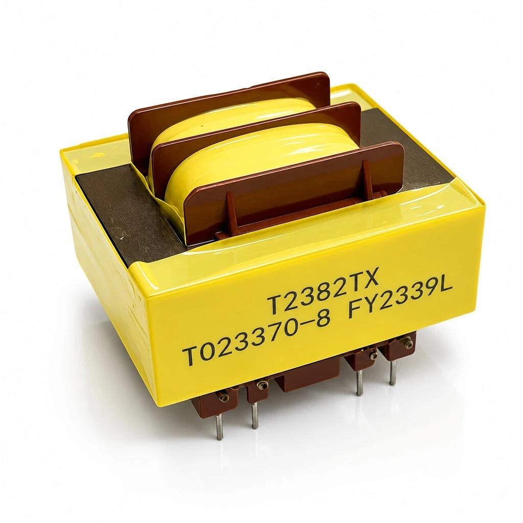
    Identification. Customer part name EI42-110V-28.3V; ZXY part number B2361; approval specification 20220922001, edition A/0. The cover is printed T2382TX / T023370-8 followed by a date code, as specified in the marking field of the approval drawing.

    Printed marking on the cover: T2382TX and T023370-8 with the date code, per the approval drawing
    Printed marking on the cover: T2382TX and T023370-8 with the date code, per the approval drawing

    The part is wound as a step-down transformer for 110 V / 60 Hz lines: two identical primary windings of 2365 turns at 0.08 mm wire are paralleled on the 1-6 and 2-7 terminals, and two secondary windings of 617 turns at 0.14 mm wire leave on 8-9 and 13-14. Each secondary gives 28.3 V AC at no load and 21.6 V AC into a 70 mA load, so one part supplies two isolated low-voltage rails, or one rail at double current when the two secondaries are paralleled.

    Three-quarter view: both rows of DIP pins, the molded bobbin cheeks and the varnish-impregnated winding
    Three-quarter view: both rows of DIP pins, the molded bobbin cheeks and the varnish-impregnated winding

    2. Product Overview

    The B2361 is a board-mounted 110 V AC step-down and isolating transformer. The two primaries are wound identically and connected in parallel to the 110 V / 60 Hz line; the two secondaries are independent, so a single part produces two galvanically isolated low-voltage rails. Because the magnetic path carries the energy and the galvanic path is broken, the low-voltage side stays separated from the mains side and ground-borne interference is kept away from downstream circuitry.

    No-load current stays within 10 mA and no-load loss within 0.8 W at rated input, which keeps standby consumption and internal heating low in equipment that is powered continuously. The winding sits on a PBT MB2830 bobbin, is taped with JY-133 and vacuum-impregnated with E962 varnish, and is closed over a 0.5 mm H18A electrical steel EI42 core. That construction fixes the insulation at Class B/F (130 / 155 °C), holds the mechanical hum down under load, and ends in rigid tinned pins for wave or hand soldering.

    Construction: EI42 core laminations on both sides of the varnish-impregnated winding, with the molded bobbin cheeks clamping the core stack
    Construction: EI42 core laminations on both sides of the varnish-impregnated winding, with the molded bobbin cheeks clamping the core stack
    Top view: the two winding sections between the core limbs, taped and impregnated, with the core stack visible on both sides
    Top view: the two winding sections between the core limbs, taped and impregnated, with the core stack visible on both sides
    Overall three-quarter view of the finished part with the printed marking, molded bobbin cheeks and both DIP pin rows
    Overall three-quarter view of the finished part with the printed marking, molded bobbin cheeks and both DIP pin rows

    3. Feature

    Dual independent primary windings — terminals 1-6 and 2-7, rated 110 V AC at 60 Hz, so the part can be fed from one line or from two.

    Two independent secondaries — terminals 8-9 and 13-14, each 28.3 V AC ±5% at no load and 21.6 V AC ±5% while delivering 70 mA.

    Low standby consumption — no-load current 10 mA max and no-load loss 0.8 W max at 110 V AC / 60 Hz.

    EI42 laminated core — 0.5 mm H18A electrical steel sheet, stacked and clamped by the bobbin cheeks.

    Class B/F insulation system — 130 °C / 155 °C rated materials throughout the winding.

    1000 V dielectric withstand — AC 1000 V at 50 Hz with a 5.0 mA leakage limit, held 60 s, between primary and secondary, primary and core, secondary and core.

    Vacuum-varnished, taped bobbin — JY-133 tape and E962 varnish lock the winding and suppress mechanical hum.

    Rigid DIP pins — 0.8 ± 0.1 mm thick, 5.0 ± 0.5 mm long, on a 20.0 ± 0.5 mm row spacing for wave or hand soldering.

    Lead-free terminations — Sn-0.3Ag-0.7Cu solderable pins.

    Compliance — CE, UL, RoHS and CCC, built from UL-listed materials (Table 4).

    Winding detail: high-purity copper windings on the bobbin, Class B/F (130 °C / 155 °C) insulation system
    Winding detail: high-purity copper windings on the bobbin, Class B/F (130 °C / 155 °C) insulation system

    4. Advantage

    Two isolated 28.3 V rails from one 110 V primary — removes the need for a second transformer on the board.

    Transformer isolation — separates the low-voltage side from the mains side and limits interference reaching downstream circuitry.

    Low 10 mA no-load current and 0.8 W no-load loss — reduces standby power and heat inside sealed enclosures.

    Vacuum impregnation of a taped PBT bobbin — suppresses mechanical hum under load.

    43.5 x 36.3 mm footprint — fits standard board outlines, and the rigid pins withstand automated insertion and soldering.

    Published approval data — winding data, dimensions and Hi-POT values are fixed in specification 20220922001, so incoming inspection can be checked against the drawing.

    Front, top, side and bottom pin views of the finished EI42-110V-28.3V transformer
    Front, top, side and bottom pin views of the finished EI42-110V-28.3V transformer

    5. Application

    The B2361 is built as a board-mounted 110 V AC step-down and isolating transformer. Typical uses are low-voltage supply and isolation stages in audio equipment, instrumentation and control electronics that need one or two isolated 28.3 V AC rails from a 110 V / 60 Hz line, board-level step-down for control boards and relay drivers, and inter-stage isolation where the mains side must stay separated from the low-voltage side.

    PCB power integration: through-hole mounting on a board-level power supply, with the transformer feeding the low-voltage section
    PCB power integration: through-hole mounting on a board-level power supply, with the transformer feeding the low-voltage section

    6. Application Specifications

    Electrical ratings are those published in the approval specification and are referred to the 60 Hz rated input at 25 °C ambient.

    6.1 Electrical specification

    ParameterConditionSpecification
    Primary rated voltage (1-6, 2-7)60 Hz110 V AC
    Primary no-load (exciting) current110 V AC, 60 Hz10 mA max
    Primary no-load (exciting) loss110 V AC, 60 Hz0.8 W max
    Secondary no-load voltage (8-9)110 V AC input28.3 V AC ±5%
    Secondary load voltage (8-9)70 mA load21.6 V AC ±5%
    Secondary no-load voltage (13-14)110 V AC input28.3 V AC ±5%
    Secondary load voltage (13-14)70 mA load21.6 V AC ±5%
    Load current per secondary—70 mA
    Dielectric withstand (Hi-POT)50 Hz, 5.0 mA limit, 60 sPrimary–secondary 1000 V AC; primary–core 1000 V AC; secondary–core 1000 V AC

    6.2 Winding construction

    WindingTerminalsWireTurnsRating
    Primary A1-62UEW Ø0.08 mm2365 TS110 V AC / 60 Hz
    Primary B2-72UEW Ø0.08 mm2365 TS110 V AC / 60 Hz
    Secondary A8-92UEW Ø0.14 mm617 TSAC 28.3 V ±5%
    Secondary B13-142UEW Ø0.14 mm617 TSAC 28.3 V ±5%

    6.3 Outline dimensions (unit: mm)

    DimensionValue (mm)
    Body length, front view43.5 max
    Body width, side view36.3 max
    Body height31.0 max
    Pin length5.0 ± 0.5
    Pin thickness0.8 ± 0.1
    Pin row spacing (bottom view)20.0 ± 0.5
    Pin pitch within each group (2-1, 7-6, 8-9, 13-14)5.0 ± 0.5
    Pins cut off and not fitted3, 4, 5, 10, 12

    6.4 Material list

    ItemSpecificationUL No.
    BobbinPBT MB2830E508398
    TapeJY-133E309872
    Wire2UEW-F, QA-1/155E355168
    Core0.5 mm H18A electrical steel sheet—
    Bar tinSn-0.3Ag-0.7Cu—
    VarnishE962E335405

    6.5 Notes on the approval data

    The approval document states the dielectric withstand in its specification section as AC 1000 V, 50 Hz, 5.0 mA leakage limit, held 60 s, applied between primary and secondary, primary and core and secondary and core; that is the requirement quoted in this listing. The test-data section of the same document records tests run at AC 3.75 kV / 1 mA / 60 s primary-to-secondary and AC 1.5 kV / 1 mA / 60 s windings-to-core, i.e. above the requirement. The secondary load voltage is likewise specified as 21.6 V AC ±5% in the specification section and as 21.6 V AC ±0.5 V in the test-data section, with the sampled units measuring 21.4 V to 21.7 V, which satisfies both. The ±5% figures are quoted in this listing; both points should be reconciled with engineering before a purchase specification is fixed.
    The approval drawing lists terminals 3, 4, 5, 10 and 12 as cut off and not fitted. The product renderings supplied with this product show a full set of pins on both rows; the pin complement of the shipped part follows the drawing, not the rendering.

    7. Quality & Testing Assurance

    Every unit is inspected for appearance and insulation resistance and measured for primary exciting current, primary exciting loss, secondary no-load voltage at 110 V AC / 60 Hz and secondary load voltage at 70 mA. Dielectric withstand is applied at AC 1000 V, 50 Hz, with a 5.0 mA leakage limit held for 60 s.

    The five-sample record filed with the approval specification shows a wide margin against the limits: exciting current 3.4 mA to 3.5 mA against a 10 mA limit, exciting loss 0.22 W against 0.8 W, no-load output 28.25 V to 28.35 V, and output at 70 mA from 21.4 V to 21.7 V. Manufacturing runs to approval specification 20220922001, edition A/0.

    CE, UL, RoHS and CCC compliance is claimed for this part and the material list carries UL file numbers for the bobbin, tape, wire and varnish. No product certificate numbers were supplied with the approval document, so none are listed; confirm them before publishing if the listing must quote certificate numbers.
    Message Form
    We Can Help You Solve Any Problem 
    Just leave your email or phone number in the contact form so we can send you a free quote for our wide range of designs!
    Related Products
    Huizhou Company Address
    Zhixiangyuan Technology Co., Ltd., 5th Floor, Building 4, Xinghe Industrial Park, Zhongkai High tech Zone, Huicheng District, Huizhou City, Guangdong Province
    Contact Us
    Contact Person: Rhea Chen
    Tel/WhatsApp: +86 13554723725
    Fax: 86-0755-23779620
    Shenzhen Company Address
    Room 202, Yingfei Haocheng Science and Technology Park, Guansheng 5th Road, Luhu Community, Guanhu Street, Longhua District, Shenzhen City, Guangdong Province, China
    Customer service
    detect