


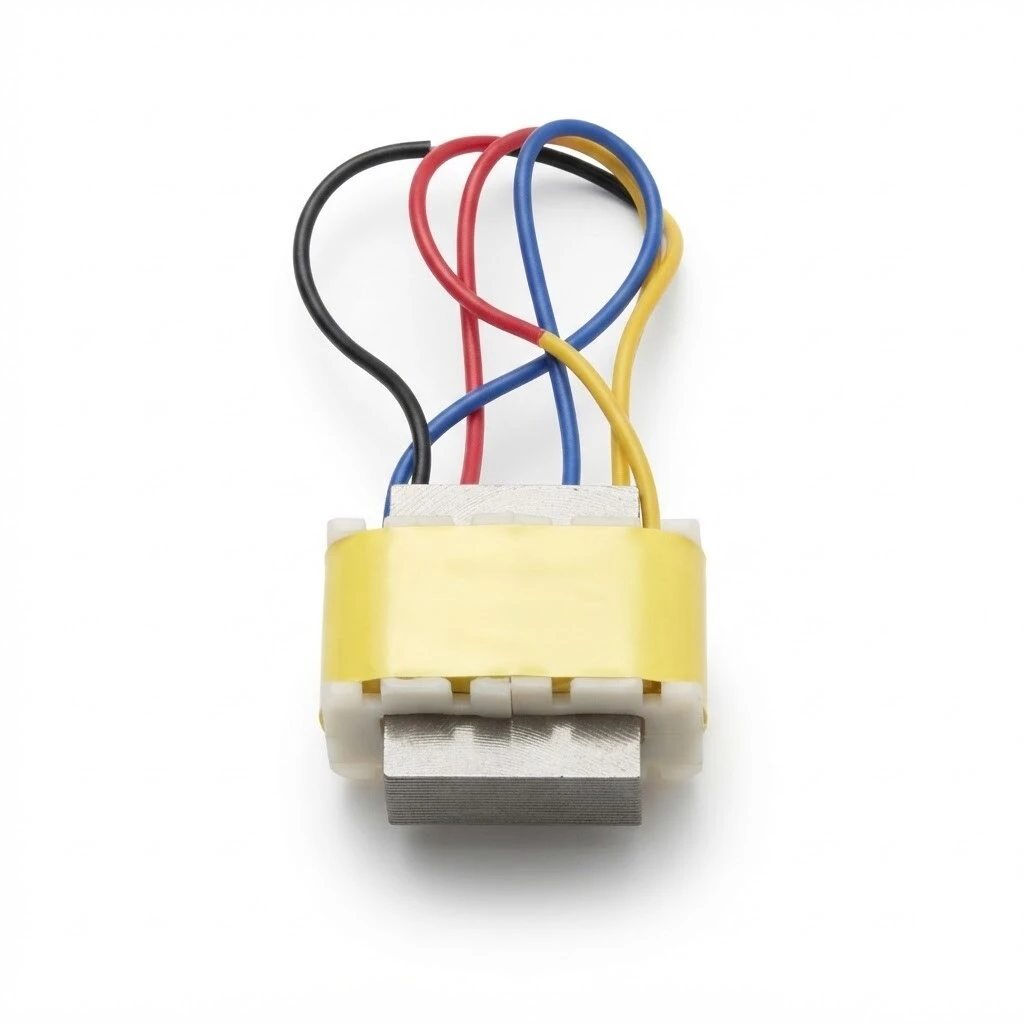
ZXY-DU135 Microphone Transformer, Flying-Lead Audio Isolation Type, 50 Hz - 20 kHz, Turns Ratio 1:1.2 / 1:2 / 1:5, Laminated Silicon Steel Core, 19.5 x 13.0 x 16.5 mm
ZXY DU135 is a microphone transformer in flying-lead form: a laminated silicon steel core, a copper winding on a nylon bobbin under an insulation wrap, and four colour-coded leads in place of PCB pins. Three turns ratios run in the same body, 1:1.2, 1:2 and 1:5, all specified over 50 Hz to 20 kHz and all rated 1500 V at 1 mA / 60 s. Body 19.5 x 16.5 mm, 13.0 mm across.
- Turns ratio 1:1.2, 1:2 or 1:5, specified over 50 Hz to 20 kHz
- Laminated silicon steel core, copper winding on a nylon bobbin
- Four colour-coded flying leads: BLACK, RED, BLUE, YELLOW
- Dielectric withstand 1500 V at 1 mA / 60 s on all three ratios
- Body 19.5 x 16.5 mm, 13.0 mm across; electrical data at 25 C
1. Product Name
ZXY DU135 microphone transformer, flying-lead type, in the 1:1.2, 1:2 or 1:5 turns ratio. Laminated silicon steel core, copper winding on a nylon bobbin under an insulation wrap, four colour-coded leads, 50 Hz to 20 kHz frequency range, body 19.5 mm long, 16.5 mm high and 13.0 mm across.
Overview. The core is silicon steel, stacked from laminations, and the coil is wound on a nylon bobbin and wrapped before the core is fitted. There are no pins: four leads come off the bobbin, BLACK and RED on one winding, BLUE and YELLOW on the other.
A flying-lead part can be routed into a microphone body, a harness or an assembly after the mechanical design is fixed, where a pinned transformer would force a board revision. The catalogue describes the outlet as adapting to a wide range of mounting and wiring scenarios, which is the practical reason to choose this form over the pinned equivalent.
2. Feature
Galvanic isolation with mains interference removed. the transformer couples the audio signal without a conductive path between the two circuits, and removes AC mains frequency interference along with it.
Voice and data coupling. wound to couple voice and data signals between stages, and between balanced and unbalanced circuits, rather than to transfer power.
50 Hz to 20 kHz frequency range. covers the speech band and the full audio band above it, so the part can sit in a microphone line or a coupling stage without setting the bandwidth limit.
Ground-loop hum removal. eliminates the hum generated when a system is grounded, which is the usual cause of noise in a signal chain built from separately earthed equipment.
Reduced interference both ways. the isolation lowers external interference pickup in balanced and in unbalanced transmission, so one part covers both wiring schemes.
Flying-lead outlet. four colour-coded leads instead of pins, for mounting and wiring scenarios where no footprint is available or the position is already fixed.
Low distortion, wide response. a design that balances speech intelligibility against audio reproduction fidelity, which is the trade a microphone transformer has to make.
Laminated silicon steel core. stacked laminations rather than a solid block, with the coil wound on a nylon bobbin and wrapped before the core is fitted.
The detail view separates the three things that carry the behaviour of this part: the lead exit and its wiring connections, the laminated core, and the insulation wrap over the coil. The wrap is the layer the 1500 V withstand rating is measured across.
3. Advantage
Three ratios in one body. 1:1.2, 1:2 and 1:5 share the same outline and the same 1500 V dielectric rating, so a product range can be covered by one qualified shape.
Wiring flexibility. a flying-lead part can be routed after the mechanical design is fixed, which a pinned transformer cannot.
Published electrical set. inductance and DC resistance are given per ratio at 25 °C, so the part can be specified against numbers rather than by listening.
Consistent dielectric margin. all three versions are rated 1500 V at a 1 mA leakage limit over 60 s, so the isolation figure does not change when the ratio does.
Insulation wrap over the coil. the winding is wrapped before the core goes on, which is the layer the withstand rating is measured across.
Colour-coded leads. BLACK, RED, BLUE and YELLOW identify the windings on the bench and in a harness, with the polarity dots on the schematic as the final reference.
Customised designs and stock. the winding can be adapted to a target ratio or level, and the standard versions are supplied factory-direct from stock.
Read the schematic before wiring the part. BLACK and RED sit on one winding with the polarity dot at the BLACK end; BLUE and YELLOW sit on the other with the dot at the BLUE end. The drawing identifies the pairs and the dots but does not mark which winding is primary, so take the pairing from the drawing and confirm the intended side before you fix a wiring order in your own drawing.
4. Application
Professional audio equipment. lavalier, camera and instrument microphones, microphone preamplifiers and audio isolation modules.
Audio systems. signal isolation and noise elimination for high-end loudspeakers, home theatre systems and car audio systems.
Communication equipment. signal coupling in telephones, fax machines, IP voice terminals and modems, where the line side must stay isolated from the equipment side.
Industrial and broadcast systems. audio signal isolation and transmission in public address and conference systems, including runs between rooms and racks.
Both assembly views show the same thing in practice: the transformer sits at the boundary between two circuits that must not share a conductor. In the chassis it is wired in on its leads beside the supply it isolates from; on the board it is soldered in at the lead ends. Neither placement needs a footprint, which is why the same part appears in both.
5. Application Specifications
The specification below is the data declared for this model: product data, the electrical table per turns ratio at 25 C, outline dimensions, and construction.
5.1 Product specification
| Item | Description |
|---|---|
| Product name | ZXY-DU135 Microphone Transformer, flying-lead type |
| Catalogue designation | ZXYDU135 (flying-lead) |
| Product type | Audio isolation / voice and data coupling transformer |
| Frequency range | 50 Hz - 20 kHz |
| Turns-ratio versions | 1 : 1.2 / 1 : 2 / 1 : 5 |
| Dielectric withstand, Hi-POT | 1500 V, leakage 1 mA, 60 s on all three versions |
| Core | Silicon steel, laminated |
| Winding / bobbin | Copper wire on a nylon bobbin |
| Termination | 4 flying leads, colour-coded BLACK / RED / BLUE / YELLOW |
| Overall dimensions | 19.5 mm long x 16.5 mm high x 13.0 mm across |
| Reference temperature | 25 °C |
5.2 Electrical specification, three turns-ratio versions, 25 C
Inductance is measured at 1 kHz with a 0.3 V test signal as a minimum; DC resistance carries a tolerance of plus or minus 15 percent; dielectric withstand is 1500 V with a 1 mA leakage limit held for 60 s.
| Turns ratio | L 1 kHz 0.3 V, 1st | L 1 kHz 0.3 V, 2nd | DCR ±15%, 1st | DCR ±15%, 2nd | Hi-POT, 1 mA 60 s |
|---|---|---|---|---|---|
| 1 : 1.2 | 3.0 H | 3.5 H | 70 Ω | 110 Ω | 1500 V |
| 1 : 2 | 1.5 H | 5 H | 120 Ω | 1.5 kΩ (1500 Ω) | 1500 V |
| 1 : 5 | 1.0 H | 20 H | 30 Ω | 400 Ω | 1500 V |
5.3 Outline dimensions
| Dimension | Marked value |
|---|---|
| Overall length | 19.5 mm |
| Overall height | 16.5 mm |
| Overall depth | 13.0 mm as marked on the catalogue outline |
| Core stack thickness | 7.0 mm as marked on the product drawing |
5.4 Construction and lead-out
| Item | Description |
|---|---|
| Core | Laminated silicon steel |
| Winding | Copper wire |
| Bobbin | Nylon |
| Insulation | Insulation wrap over the coil, as labelled on the detail graphic |
| Leads | 4 colour-coded flying leads: BLACK, RED, BLUE, YELLOW |
| Termination style | Flying lead, no PCB pins |
| Polarity | Marked by the dots on the schematic |
6. Quality & Testing Assurance
The limits below are the ones the same specification sheet states for this model. The three turns-ratio versions share one set of limits except for the inductance and resistance values themselves.
| Test item | Condition / limit |
|---|---|
| Inductance L | 1 kHz, 0.3 V test signal, minimum values per Table 1 |
| DC resistance, DCR | Tolerance ±15% |
| Dielectric withstand, Hi-POT | 1500 V, leakage limit 1 mA, held 60 s |
| Reference temperature | 25 °C for all electrical parameters |
Winding insulation is an insulation wrap over the coil, and the leads are colour-coded so the windings can be identified without a meter.
Brand / manufacturer: ZXY, Shenzhen Zhixiangyuan Electronics Co., Ltd. and Huizhou Zhixiangyuan Technology Co., Ltd. http://www.zxycoil.com