loading

ZXY: 26 Years of Excellence as a Leading Transformer and Inductor Manufacturer ・ One-Stop Solutions

ZXY-EI16 Fly-Lead Microphone Transformer, Audio Isolation Type, 50 Hz - 20 kHz, 1:5 and 1:6 Turns Ratio, EI16 Laminated Steel Core, 16.5 x 14.5 x 14.5 mm 1
ZXY-EI16 Fly-Lead Microphone Transformer, Audio Isolation Type, 50 Hz - 20 kHz, 1:5 and 1:6 Turns Ratio, EI16 Laminated Steel Core, 16.5 x 14.5 x 14.5 mm 2
ZXY-EI16 Fly-Lead Microphone Transformer, Audio Isolation Type, 50 Hz - 20 kHz, 1:5 and 1:6 Turns Ratio, EI16 Laminated Steel Core, 16.5 x 14.5 x 14.5 mm 3
ZXY-EI16 Fly-Lead Microphone Transformer, Audio Isolation Type, 50 Hz - 20 kHz, 1:5 and 1:6 Turns Ratio, EI16 Laminated Steel Core, 16.5 x 14.5 x 14.5 mm 4
ZXY-EI16 Fly-Lead Microphone Transformer, Audio Isolation Type, 50 Hz - 20 kHz, 1:5 and 1:6 Turns Ratio, EI16 Laminated Steel Core, 16.5 x 14.5 x 14.5 mm 5
ZXY-EI16 Fly-Lead Microphone Transformer, Audio Isolation Type, 50 Hz - 20 kHz, 1:5 and 1:6 Turns Ratio, EI16 Laminated Steel Core, 16.5 x 14.5 x 14.5 mm 6
ZXY-EI16 Fly-Lead Microphone Transformer, Audio Isolation Type, 50 Hz - 20 kHz, 1:5 and 1:6 Turns Ratio, EI16 Laminated Steel Core, 16.5 x 14.5 x 14.5 mm 7
ZXY-EI16 Fly-Lead Microphone Transformer, Audio Isolation Type, 50 Hz - 20 kHz, 1:5 and 1:6 Turns Ratio, EI16 Laminated Steel Core, 16.5 x 14.5 x 14.5 mm 8
ZXY-EI16 Fly-Lead Microphone Transformer, Audio Isolation Type, 50 Hz - 20 kHz, 1:5 and 1:6 Turns Ratio, EI16 Laminated Steel Core, 16.5 x 14.5 x 14.5 mm 1
ZXY-EI16 Fly-Lead Microphone Transformer, Audio Isolation Type, 50 Hz - 20 kHz, 1:5 and 1:6 Turns Ratio, EI16 Laminated Steel Core, 16.5 x 14.5 x 14.5 mm 2
ZXY-EI16 Fly-Lead Microphone Transformer, Audio Isolation Type, 50 Hz - 20 kHz, 1:5 and 1:6 Turns Ratio, EI16 Laminated Steel Core, 16.5 x 14.5 x 14.5 mm 3
ZXY-EI16 Fly-Lead Microphone Transformer, Audio Isolation Type, 50 Hz - 20 kHz, 1:5 and 1:6 Turns Ratio, EI16 Laminated Steel Core, 16.5 x 14.5 x 14.5 mm 4
ZXY-EI16 Fly-Lead Microphone Transformer, Audio Isolation Type, 50 Hz - 20 kHz, 1:5 and 1:6 Turns Ratio, EI16 Laminated Steel Core, 16.5 x 14.5 x 14.5 mm 5
ZXY-EI16 Fly-Lead Microphone Transformer, Audio Isolation Type, 50 Hz - 20 kHz, 1:5 and 1:6 Turns Ratio, EI16 Laminated Steel Core, 16.5 x 14.5 x 14.5 mm 6
ZXY-EI16 Fly-Lead Microphone Transformer, Audio Isolation Type, 50 Hz - 20 kHz, 1:5 and 1:6 Turns Ratio, EI16 Laminated Steel Core, 16.5 x 14.5 x 14.5 mm 7
ZXY-EI16 Fly-Lead Microphone Transformer, Audio Isolation Type, 50 Hz - 20 kHz, 1:5 and 1:6 Turns Ratio, EI16 Laminated Steel Core, 16.5 x 14.5 x 14.5 mm 8

ZXY-EI16 Fly-Lead Microphone Transformer, Audio Isolation Type, 50 Hz - 20 kHz, 1:5 and 1:6 Turns Ratio, EI16 Laminated Steel Core, 16.5 x 14.5 x 14.5 mm

ZXY-EI16 mic transformer | fly lead | 50 Hz - 20 kHz | 1:5 B2456, 1:6 B2577 | EI16 core

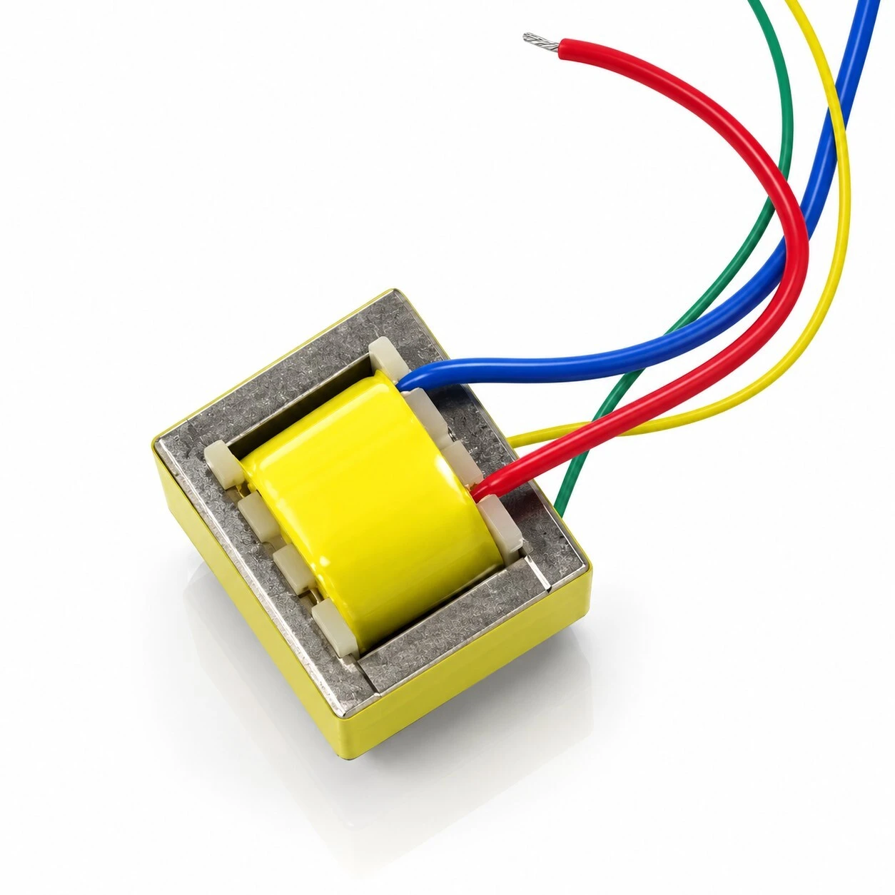
ZXY EI16 is a microphone transformer in fly-lead form: an EI16 laminated steel core, a coil on an insulated bobbin under a protective tape wrap, and four colour-coded leads in place of PCB pins. Two turns-ratio versions are standard, 1:5 as type B2456 and 1:6 as type B2577, both specified over 50 Hz to 20 kHz and both rated 1500 V at 1 mA / 60 s. Body 16.5 x 14.5 x 14.5 mm.

ZXY-EI16, top view: yellow tape wrap over the coil inside the EI16 lamination frame, four colour-coded fly leads
KEY HIGHLIGHTS
  • Turns ratio 1:5 (B2456) or 1:6 (B2577), specified over 50 Hz to 20 kHz
  • EI16 laminated steel core, insulated bobbin, protective tape wrap
  • BLUE / YELLOW primary, RED / GREEN secondary, phase marked by dots
  • Dielectric withstand 1500 V at 1 mA / 60 s on both versions
  • Body 16.5 x 14.5 x 14.5 mm; electrical data at 25 °C
The source sheet prints the same header twice on the two inductance columns and twice on the two DC resistance columns. It also states that winding 1 is the primary (microphone side) and winding 2 the secondary (console side), so the columns are given here by winding rather than left ambiguous. The inductance units are the ones printed, and they differ between the two types: B2456 is given in mH (30 mH and 800 mH) and B2577 in H (0.5 H and 18.0 H). Nothing has been converted; compare the two rows in their printed units.
5.0
Model:
ZXY-EI16
Frequency Range:
50 Hz - 20 kHz
Lead Assignment:
BLUE/YELLOW primary, RED/GREEN secondary
Type Code:
B2456 (1
Dielectric Withstand:
1500 V, 1 mA, 60 s
Dimensions:
16.5 x 14.5 x 14.5 mm
Core:
EI16 laminated steel
Termination:
4 colour-coded fly leads
Turns Ratio:
1
Product Type:
Microphone transformer, fly-lead audio isolation
design customization

    oops...!

    no product data.

    Go to homepage
    Secondary Leads
    RED phase, GREEN return
    Primary Leads
    BLUE phase, YELLOW return
    Windings
    Primary and secondary
    Circuit Function
    Voice and data coupling, signal isolation
    Type Code 1
    6
    Overall Length
    16.5 mm
    Catalogue Designation
    ZXYEI16 fly-lead
    Inductance Test
    1 kHz, 0.3 V minimum
    Lead Colours
    BLUE, YELLOW, RED, GREEN
    DCR Tolerance
    ±15%
    Overall Depth
    14.5 mm
    Overall Height
    14.5 mm
    Model
    ZXY-EI16
    Frequency Range
    50 Hz - 20 kHz
    Product Type
    Microphone / audio isolation transformer
    Termination
    4 colour-coded fly leads
    Bobbin
    Insulated, with winding insulation and tape
    Turns Ratio
    1
    Core
    EI16 laminated steel core

    1. Product Name

    ZXY EI16 fly-lead audio isolation microphone transformer, in the 1:5 version type B2456 or the 1:6 version type B2577. EI16 laminated steel core, insulated bobbin with a protective tape wrap over the coil, four colour-coded leads, 50 Hz to 20 kHz, body 16.5 mm long, 14.5 mm high and 14.5 mm deep.

    ZXY-EI16, top view: yellow tape wrap over the coil inside the EI16 lamination frame, four colour-coded fly leads
    ZXY-EI16, top view: yellow tape wrap over the coil inside the EI16 lamination frame, four colour-coded fly leads
    Four viewing angles of the same body: front, side, top and three-quarter
    Four viewing angles of the same body: front, side, top and three-quarter

    Overview. The core is an EI16 lamination stack; the coil sits on an insulated bobbin inside the centre limb and is finished with a tape wrap. There are no pins, so what leaves the part is four leads: BLUE and YELLOW from the primary, RED and GREEN from the secondary.

    A fly-lead part can be routed into a microphone body, a harness or an assembly after the mechanical design is fixed, where a pinned transformer would force a board revision. The two standard ratios cover the usual step-up requirements, so a custom winding is only needed when neither fits.

    2. Feature

    EI16 laminated steel core. the core is an EI16 lamination stack rather than a solid block, wound on an insulated bobbin and finished with a protective tape wrap over the coil.

    50 Hz to 20 kHz frequency range. covers the whole audible band, so the part can sit in a microphone line or a coupling stage without setting the bandwidth limit itself.

    Voice and data coupling. wound to couple voice and data signals between stages and across an isolation barrier, not to transfer power.

    Two standard turns-ratio versions. 1:5 as type B2456 and 1:6 as type B2577, so the step-up can be matched to the circuit without a custom design.

    Low distortion, wide-band design. the winding is designed to hold speech intelligibility and audio reproduction fidelity at the same time.

    Dielectric withstand 1500 V. tested at a 1 mA leakage limit for 60 s, which is the barrier the isolation claim rests on.

    Four colour-coded leads. BLUE and YELLOW on the primary, RED and GREEN on the secondary, with the phase end of each winding marked by a dot on the wiring diagram, so the part can be wired correctly without a meter.

    Compact EI16 outline. 16.5 mm long, 14.5 mm high and 14.5 mm deep, small enough to sit inside a microphone body or beside a connector.

    Side view: the coil face between the two lamination limbs, leads brought out horizontally
    Side view: the coil face between the two lamination limbs, leads brought out horizontally

    The side view shows the construction as a stack rather than a potted block: the two outer lamination limbs, the bobbin flange between them, and the coil face under its tape wrap. The leads leave the bobbin at the flange, which is what keeps the solder joint outside the winding window.

    3. Advantage

    Protects upstream equipment. as an isolating transformer it keeps the output stage of the preceding equipment from being damaged by what happens on the other side of the barrier.

    Removes ground-loop hum. resolves the AC hum that appears when a system is earthed at more than one point, which is the usual cause of noise in a chain built from separately powered units.

    Rejects interference both ways. reduces external interference pickup in balanced and in unbalanced transmission, so one part covers both wiring schemes.

    Installation flexibility. the fly-lead construction adapts to a wide range of mounting and wiring scenarios, including positions where no footprint is available.

    Audio quality held in balance. low distortion together with a wide frequency response keeps speech intelligible without flattening the audio band.

    Custom builds and stock. customised designs are available, and the standard versions are supplied factory-direct with stock on hand.

    Wiring diagram: BLUE phase and YELLOW return on the primary (microphone side), RED phase and GREEN return on the secondary (console side), dots marking phase
    Wiring diagram: BLUE phase and YELLOW return on the primary (microphone side), RED phase and GREEN return on the secondary (console side), dots marking phase

    Wire the part from the diagram, not from the wire order. BLUE is the phase lead on the primary and YELLOW its return; RED is the phase lead on the secondary and GREEN its return. The dots mark the phase end of each winding, so the two windings can be connected in the intended polarity rather than by trial.

    4. Application

    Professional audio equipment. lavalier microphones, camera microphones, instrument microphones, microphone preamplifiers and audio isolation modules.

    Audio systems. signal isolation and noise elimination for high-end loudspeakers, home theatre systems and car audio.

    Communication equipment. signal coupling for telephones, fax machines, VoIP terminals and modems, where the line side must stay isolated from the equipment side.

    Industrial and broadcast systems. audio signal isolation and transmission in public-address and conference systems, including runs between rooms and racks.

    Three-quarter view from the lead side, lamination stack and bobbin flanges in profile
    Three-quarter view from the lead side, lamination stack and bobbin flanges in profile
    Top three-quarter view: lead exit at the bobbin and the tape wrap over the winding
    Top three-quarter view: lead exit at the bobbin and the tape wrap over the winding

    Both views are of the same body from the lead side, and they show what a layout has to allow for: the leads leave upwards from the bobbin, so the part needs clearance above the flange rather than a footprint under it. That is the reason this construction is chosen for microphone bodies and harness assemblies.

    5. Application Specifications

    The specification below is the data declared for this model: general data, the electrical table per type at 25 °C, outline dimensions, and the lead assignment.

    5.1 General specification

    ItemValue
    Product nameZXY EI16 fly-lead audio isolation microphone transformer
    Model / seriesZXYEI16 (fly-lead)
    Type codesB2456 for the 1:5 version, B2577 for the 1:6 version
    Product categoryMicrophone transformer / audio isolation transformer
    Circuit functionVoice and data coupling transformer; signal isolation
    CoreEI16 laminated steel core
    BobbinInsulated bobbin with winding insulation and protective tape
    WindingsTwo windings, primary and secondary, ratio 1:5 or 1:6
    Frequency range50 Hz - 20 kHz, the audible range
    Termination4 colour-coded fly leads
    Overall size16.5 mm long x 14.5 mm high x 14.5 mm deep
    Dielectric withstandHi-POT 1500 V, 1 mA, 60 s
    Reference temperature25 °C
    Design serviceCustomised designs available

    5.2 Electrical specification, two turns-ratio versions, 25 °C

    Inductance is measured at 1 kHz with a 0.3 V test signal as a minimum; DC resistance carries a tolerance of plus or minus 15 percent; dielectric withstand is 1500 V with a 1 mA leakage limit held for 60 s. Winding 1 is the primary, the microphone side; winding 2 is the secondary, the console side.

    TypeTurns ratioL, wdg 1 priL, wdg 2 secDCR, wdg 1 priDCR, wdg 2 secHi-POT
    B24561:530 mH800 mH1.6 Ω25 Ω1500 V
    B25771:60.5 H18.0 H20 Ω715 Ω1500 V
    The source sheet prints the same header twice on the two inductance columns and twice on the two DC resistance columns. It also states that winding 1 is the primary (microphone side) and winding 2 the secondary (console side), so the columns are given here by winding rather than left ambiguous. The inductance units are the ones printed, and they differ between the two types: B2456 is given in mH (30 mH and 800 mH) and B2577 in H (0.5 H and 18.0 H). Nothing has been converted; compare the two rows in their printed units.

    5.3 Outline dimensions

    DimensionMarked value
    Length16.5 mm across the body in top view
    Height14.5 mm in front view
    Depth14.5 mm in top view
    Outline drawing, unit mm: 16.5 mm across the body, 14.5 mm high in front view, 14.5 mm deep in top view
    Outline drawing, unit mm: 16.5 mm across the body, 14.5 mm high in front view, 14.5 mm deep in top view
    The same view with the 16.5 mm and 14.5 mm dimensions marked on the body
    The same view with the 16.5 mm and 14.5 mm dimensions marked on the body
    The source states the overall size as 16.5 × 14.5 × 14.5 mm without naming which dimension is which. The three-view drawing settles it: 16.5 mm is measured across the body in the top view, and 14.5 mm is the vertical height in the front view and the depth in the top view. The three figures are therefore listed below as length, height and depth in that order.

    5.4 Lead wire and winding assignment

    Lead colourWindingMarking on wiring diagram
    BLUEPrimary, microphone sidePhase
    YELLOWPrimary, microphone sideReturn
    REDSecondary, console sidePhase
    GREENSecondary, console sideReturn
    Four leads, colour-coded, with the phase end of each winding marked by a dot on the wiring diagram. BLUE is the phase lead and YELLOW the return on the primary, which is the microphone side; RED is the phase lead and GREEN the return on the secondary, which is the console side. The assignment is the one the source table states, not an inference from the drawing.

    6. Quality & Testing Assurance

    The limits below are the acceptance limits the specification sheet states for both standard types. They share one set of limits except for the inductance and resistance values themselves.

    ParameterSpecificationTest / reference condition
    Turns ratio1:5 (B2456) or 1:6 (B2577)25 °C
    Inductance, winding 1 (primary)30 mH min on B2456, 0.5 H min on B25771 kHz, 0.3 V
    Inductance, winding 2 (secondary)800 mH min on B2456, 18.0 H min on B25771 kHz, 0.3 V
    DCR, winding 1 (primary)1.6 Ω on B2456, 20 Ω on B2577, tolerance ±15%25 °C
    DCR, winding 2 (secondary)25 Ω on B2456, 715 Ω on B2577, tolerance ±15%25 °C
    Dielectric withstand, Hi-POT1500 V1 mA, 60 s

    Winding insulation is the insulated bobbin plus a protective tape wrap over the coil, and the leads are colour-coded so the windings can be identified without a meter.

    This page quotes the construction, dimensional, electrical and test data that the specification declares for ZXY-EI16. That document states no weight, no MOQ and no price, so none of those are given here. It also carries no certificate number, so the CCC, CE, RoHS and UL marks that appear in some of the supplied renderings are not claimed on this page and the artwork carrying them is not used. The two type codes, B2456 and B2577, are the ratio identifiers: B2456 is the 1:5 version and B2577 the 1:6 version.

    Brand / manufacturer: ZXY, Shenzhen Zhixiangyuan Electronics Co., Ltd. and Huizhou Zhixiangyuan Technology Co., Ltd. http://www.zxycoil.com

    Message Form
    We Can Help You Solve Any Problem 
    Just leave your email or phone number in the contact form so we can send you a free quote for our wide range of designs!
    Related Products
    Huizhou Company Address
    Zhixiangyuan Technology Co., Ltd., 5th Floor, Building 4, Xinghe Industrial Park, Zhongkai High tech Zone, Huicheng District, Huizhou City, Guangdong Province
    Contact Us
    Contact Person: Rhea Chen
    Tel/WhatsApp: +86 13554723725
    Fax: 86-0755-23779620
    Shenzhen Company Address
    Room 202, Yingfei Haocheng Science and Technology Park, Guansheng 5th Road, Luhu Community, Guanhu Street, Longhua District, Shenzhen City, Guangdong Province, China
    Customer service
    detect