


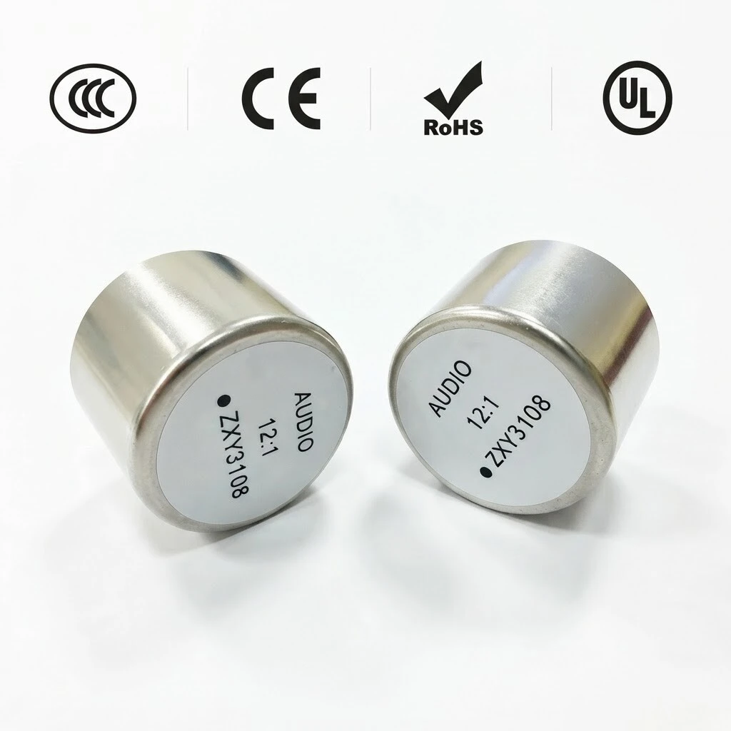
ZXY-3108 12:1 Audio Isolation Transformer - 140 kOhm Permalloy Core | Mu-Metal Shielded | Vertical 4+4 Pin Through-Hole | Hi-Fi Valve Amplifier
The ZXY-3108 is a 12:1 audio isolation transformer built on a permalloy core and sealed in a mu-metal case. It combines a 140 kOhm primary impedance with a 12:1 (N1:N2) turns ratio to provide galvanic isolation and effective common-mode noise rejection in high-impedance, high-fidelity audio signal paths. The unit is supplied as a 31.0 mm x 22.0 mm vertical-mount body with a 4 + 4 pin arrangement for through-hole PCB layouts.
- 12:1 turns ratio (N1:N2), ±2% at 20 kHz, 1 V
- 140 kΩ ±10% primary impedance, DCR 4.6 kΩ / 62 Ω
- Permalloy core in a mu-metal case with electrostatic shield on pin 2
- AC 1250 V primary-to-secondary, 100 MΩ insulation resistance
- 31.0 mm x 22.0 mm, 4 + 4 pins, approx. 20 g, RoHS compliant
1. Product Overview
The ZXY-3108 is a 12:1 audio isolation transformer built on a permalloy core and sealed in a mu-metal case. It combines a 140 kOhm primary impedance with a 12:1 (N1:N2) turns ratio to provide galvanic isolation and effective common-mode noise rejection in high-impedance, high-fidelity audio signal paths. The unit is supplied as a 31.0 mm x 22.0 mm vertical-mount body with a 4 + 4 pin arrangement for through-hole PCB layouts.
Figure 1 — ZXY-3108 12:1 audio isolation transformer with CCC / CE / RoHS / UL markings.
General information
| Item | Specification |
|---|---|
| Model | ZXY-3108 (12:1 turns ratio) |
| Our part number | ZXY3108-12:1 |
| Customer part number | G2505 |
| Type | Vertical-mount audio isolation transformer, 4 + 4 pins |
| Manufacturer | Shenzhen Zhixiangyuan Electronics Co., Ltd. |
The body is finished in satin metal with a printed identification label on the top face, on which pin 1 is marked with a white dot. The nameplate identifies the model, the 12:1 ratio and the pin 1 position, which helps to avoid wiring errors during assembly and field service.
Figure 2 — Top face with the printed identification label (pin 1 marked) and bottom view of the 4 + 4 pin layout.
2. Features
- Turns ratio (N1:N2) — 12:1 ±2% at 20 kHz, 1 V.
- Impedance — 140 kΩ ±10% at 1 kHz, 1 V, measured with a 1.0 kΩ load.
- Low DC resistance — 4.6 kΩ ±15% (pins 1-4) and 62 Ω ±15% (pins 5-8).
- Electrostatic shield — Between the primary and secondary windings, brought out on pin 2.
- Permalloy core — Mu-metal case for magnetic shielding (pins 3 and 6).
- Insulation and wire — Interleaved insulation of 2 layers; primary wire 2UEW-F 0.045 mm x 1P, secondary wire 2UEW-F 0.11 mm x 1P.
- Dielectric strength — Primary-to-secondary: AC 1250 V, 1 mA, 2 s, 50 Hz.
- Insulation resistance — 100 MΩ minimum at DC 500 V.
- Operating temperature — -25 °C to +85 °C.
- Weight and compliance — Approx. 20 g; RoHS compliant.
Figure 3 — Vertical-mount construction with sealed mu-metal case.
3. Advantages
The permalloy (high-permeability nickel-iron) core and the mu-metal case give the ZXY-3108 high primary inductance together with effective magnetic shielding. The result is low insertion loss, low distortion and a wide, even frequency response, with strong suppression of common-mode noise picked up along the signal cable.
Two-layer interleaved insulation and an electrostatic shield between the windings reduce capacitive coupling and keep the 12:1 ratio consistent from unit to unit, while the step-down ratio matches high-impedance valve and tube stages to lower-impedance line inputs. The 31 mm x 22 mm body and 4 + 4 pin pattern save board space and suit automatic insertion, and all wound components are UL-recognised.
Because the windings are wound on the permalloy core and the assembly is epoxy-sealed and varnish-impregnated, electrical performance stays stable within the rated ambient range and the finished part resists moisture, mechanical stress and vibration in transport and in service.
Figure 4 — ZXY3108 12:1 audio isolation units, satin mu-metal case and printed top label.
4. Applications
The ZXY-3108 is designed for signal isolation wherever ground loops or common-mode noise must be removed:
- Hi-fi valve amplifiers — Tube amplifiers, pre-amplifiers and inter-stage coupling.
- Line-level isolation — Line-level isolation and ground-loop breaking in audio systems.
- Balanced-to-unbalanced conversion — Mixers, interfaces and audio processors.
- Instrumentation inputs — Galvanically isolated inputs for instrumentation and professional audio equipment.
- PCB-level isolation — Isolation in measuring, control and communication equipment.
Figure 5 — Isolation transformers in a valve amplifier signal path.
Figure 6 — PCB-level mounting with twisted-pair flying connections.
5. Specifications
Electrical data are specified at 25 °C and follow the customer specification drawing for ZXY3108-12:1, edition A/0. All dimensions are in millimetres; pin numbering is shown viewed from the bottom of the unit.
5.1 Electrical Specifications (at 25 °C)
| Parameter | Value | Conditions |
|---|---|---|
| Impedance | 140 kΩ ±10% | 1.0 kΩ load, 1 kHz, 1 V |
| Turns ratio (N1:N2) | 12:1 ±2% | 20 kHz, 1 V |
| DCR (pins 1-4) | 4.6 kΩ ±15% | at 25 °C |
| DCR (pins 5-8) | 62 Ω ±15% | at 25 °C |
| Hi-Pot (PRI-SEC) | AC 1250 V | 1 mA, T = 2 s, AC 50 Hz |
| Insulation resistance (PRI-SEC) | 100 MΩ MIN | DC 500 V |
5.2 Construction and Specification
| Item | Specification |
|---|---|
| Core | Permalloy |
| Construction | Vertical mount, 4 + 4 pins |
| Primary inductance (1-4) | 3990.5 TS |
| Primary copper wire | 2UEW-F 0.045 mm x 1P |
| Secondary copper wire | 2UEW-F 0.11 mm x 1P |
| Interleaved insulation | 2 layers (tape 2 TS) |
| Weight | Approx. 20 g |
| Operating temperature | -25 °C to +85 °C |
| RoHS | Compliant |
Primary inductance is quoted as 3990.5 TS in the customer specification sheet.
5.3 Mechanical Dimensions (unit: mm)
| Dimension | Value |
|---|---|
| Overall diameter | Ø31.0 ± 1.0 |
| Total height | 22.0 ± 1.0 |
| Pin pitch, front view | 5.0 ± 0.3 |
| Pin row spacing, side view | 12.5 ± 0.5 |
| Pin circle / body diameter | Ø31 |
| Pin arrangement | 8 pin positions, 4 + 4, vertical through-hole; pin 7 trimmed as shown in the drawing |
Figure 7 — Product views, sealed case construction and pin layout.
5.4 Pin Function
| Pin | Function |
|---|---|
| 1 | N1 start (primary) |
| 2 | Shield — E1 |
| 3 | Metal case |
| 4 | N1 finish (primary) |
| 5 | N2 finish (secondary) |
| 6 | Core |
| 7 | E2 (trimmed as shown in the drawing) |
| 8 | N2 start (secondary) |
Pins 1 and 8 are the dotted (start) terminals. The specification artwork designates the shield, case and core connections E1 (pin 2), E3 (pin 3), E4 (pin 6) and E2 (pin 7). Pin 1 is identified by the white dot on the top label.
5.5 Material List
| No. | Description | Specification | UL No. |
|---|---|---|---|
| 1 | Bobbin | T375HF | E59481 |
| 2 | Tape | JY-133 | E309872 |
| 3 | Wire | QA-1/155, 2UEW-F | E355168 |
| 4 | Bar tin | Sn-0.3Ag-0.7Cu | — |
| 5 | Core | Permalloy | — |
| 6 | Mu-metal case | Permalloy | — |
| 7 | Epoxy | FC-500 | — |
| 8 | Varnish | E962 | E335405 |
6. Quality & Testing Assurance
- Inspection — Every unit is manufactured to specification G2505 and verified against the electrical table: turns ratio, impedance, DCR, dielectric strength (Hi-Pot) and insulation resistance.
- Protection — Windings are interleaved with two insulating layers, epoxy-sealed and varnish-impregnated to protect the assembly against moisture, mechanical stress and vibration.
- UL-recognised components — Bobbin UL E59481, tape UL E309872, wire UL E355168, varnish UL E335405.
- Environmental — RoHS compliant and rated for operation from -25 °C to +85 °C.
The unit is built to the customer specification drawing ZXY3108-12:1 (specification no. 20240424001, edition A/0, dated 24 April 2024), which defines the dimensions, electrical values and material list reproduced in this description.
Figure 8 — Specification summary: mechanical dimensions, pin function and electrical table.