


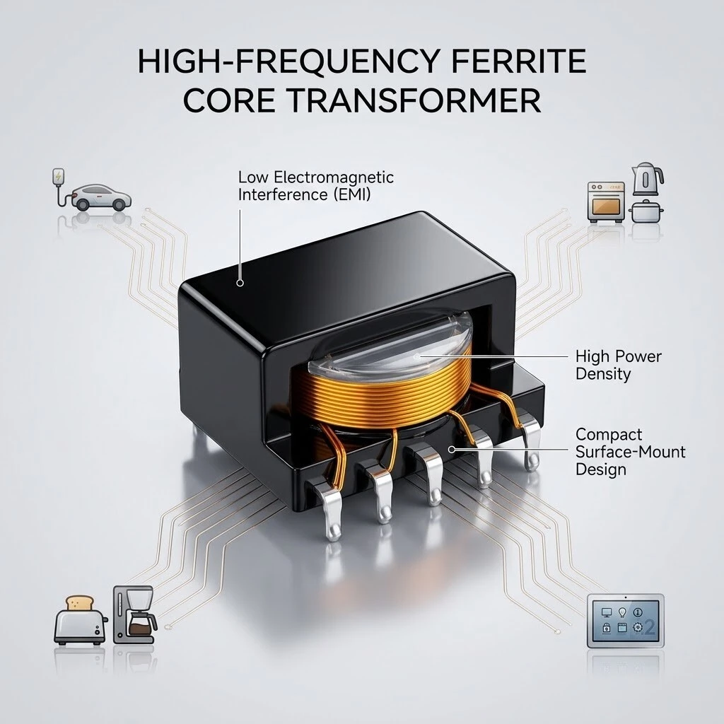
ER14.5 High-Frequency Ferrite Core SMD Transformer, NiZn Pulse Transformer for AC-DC Power Supplies
ER14.5 is a high-frequency ferrite core transformer for surface-mount power supplies: a NiZn power ferrite core, copper windings on terminals 1-3 and 4-6, an encapsulated capsule case and tin-plated lead-free gullwing terminals. Body 15.0 x 12.0 x 7.0 mm maximum, primary specified from 6 V to 305 V and secondary from 1.8 V to 55 V, leakage inductance 0.32 µH to 5.8 µH at 1 kHz and 0.25 V. Series declared from 1 Hz to 1 MHz and -45 °C to +125 °C.
- ER14.5 NiZn power ferrite core in a 15.0 x 12.0 x 7.0 mm body
- Primary 6 V to 305 V on terminals 1-3, secondary 1.8 V to 55 V on 4-6
- DC resistance 2.8 Ω to 82 Ω and 0.02 Ω to 12.8 Ω at 25 °C
- Leakage inductance 0.32 µH to 5.8 µH at 1 kHz and 0.25 V
- Encapsulated capsule case, tin-plated lead-free surface-mount terminals
- Operating temperature -45 °C to +125 °C, storage humidity 30% to 70%
1. Product Name
ER14.5 high-frequency ferrite core transformer for surface-mount power supplies. NiZn power ferrite core, copper windings on terminals 1-3 and 4-6, encapsulated capsule case, tin-plated lead-free gullwing terminals, horizontal mount, body 15.0 x 12.0 x 7.0 mm maximum.
The core. ER14.5 is the core size, and the material is nickel-zinc ferrite. NiZn is chosen for switching work because its resistivity is high enough that the eddy currents induced inside the core itself stay small; what is left is hysteresis loss, which is a property of the material and the flux swing rather than of the winding. The two halves sit either side of the bobbin and the case closes over both.
The reason this matters at 15.0 mm across is that the core has to carry the flux at the switching frequency rather than at a mains frequency. Drive the same power at a higher frequency and the flux swing per cycle falls in proportion, so the core cross-section falls with it - which is how a body this size does the job of a laminated part many times larger.
2. Construction & Materials
The case. A moulded shell closes over the assembled core and coil. It holds the core halves and the bobbin against vibration, it keeps moisture and flux residue away from the winding, and it gives the part a hard outside dimension so a placement nozzle has a flat face to land on. The terminals come through the case wall and are formed into feet outside it.
The terminals are tin plated and lead free. That is a process decision as much as a materials one: a tin finish wets on a lead-free reflow profile without a separate pre-tinning step, and the formed foot gives the solder joint a fillet on three sides instead of a butt joint.
The same body is wound in different configurations for different designs. What changes between them is the turns count, the wire gauge, the ratio between the two windings, and where the terminal rows are placed; what stays the same is the core, the case and the way the part sits on the board. That is why the electrical table in section 5.3 is given as a window rather than as one set of numbers.
3. Feature
NiZn power ferrite core.. ER14.5 core in nickel-zinc ferrite, the material chosen for high-frequency switching because its resistivity keeps eddy current loss down as the switching frequency rises.
Horizontal surface-mount body.. The body lies flat on the board and the terminals are formed into feet, so the part is placed by the same machine that places the rest of the board and needs no through-hole step.
Encapsulated capsule case.. A moulded shell covers the core and the winding, which holds the coil in place, keeps moisture off the winding and gives the body a defined outside dimension for the pick-and-place nozzle.
Tin-plated lead-free terminals.. Terminals are tin plated and lead free, so the part goes through a lead-free reflow profile without a separate finish requirement.
Wound to the customer's design.. Turns, wire gauge, ratio and inductance are set per order; the ranges in section 5 are the window the factory works in, not a fixed catalogue winding.
4. Application
AC-DC power supplies and adapters.. The primary side takes the rectified mains rail and the secondary feeds the output stage, with the winding set to the controller's switching frequency.
Home appliances.. Kettles, cookers, toasters and coffee machines now carry a small switch-mode board for their control panel, and this is the body that sits on it.
Smart thermostats and control panels.. A wall panel runs from a low-voltage rail and has to be isolated from the load it switches, which is the secondary winding's job here.
EV charging and auxiliary supplies.. On-board and charger-side auxiliary rails need a small isolated supply for the control and measurement circuit, which is where the encapsulated body is used.
Industrial control and isolated interfaces.. Where two boards sit at different ground potentials, the transformer carries the signal or the auxiliary power across the boundary without a conductor joining the two grounds.
The two board views are the same part seen from either side. The feet sit flat on their pads and the body stands clear of the board, so the encapsulant does not foul the solder mask and the winding has air on all four sides. Nothing about the position is adjustable once the footprint is drawn, so the terminal row spacing in section 5.4 is what the layout is built from.
5. Application Specifications
The data below separates three things that are often run together: what the series is rated across, what the winding of this core is specified to, and the outline the part is built to. The ranges are the factory window for a custom winding, not a fixed catalogue part.
5.1 Product specification
| Item | Value |
|---|---|
| Product name | ER14.5 high-frequency ferrite core SMD transformer |
| Core | ER14.5, NiZn power ferrite |
| Winding | Copper, precision wound; primary on 1-3, secondary on 4-6 |
| Case | Encapsulated capsule case over core and winding |
| Terminals | Tin-plated, lead-free, surface mount |
| Mounting | Horizontal, gullwing terminals on the board |
| Body size | 15.0 x 12.0 x 7.0 mm maximum |
| Operating frequency range | 1 Hz to 1 MHz, declared for the series |
| Output power, series | 0.5 W to 5000 W |
| Output current, series | 0.005 A to 160 A |
| Primary voltage, 1-3 | 6 V to 305 V |
| Secondary voltage, 4-6 | 1.8 V to 55 V |
| DC resistance, 1-3 | 2.8 Ω to 82 Ω |
| DC resistance, 4-6 | 0.02 Ω to 12.8 Ω |
| Leakage inductance | 0.32 µH to 5.8 µH |
| Operating temperature | -45 °C to +125 °C |
| Storage temperature | +1 °C to +105 °C, as declared |
| Storage humidity | 30% to 70% |
| Reference conditions | 1 kHz, 0.25 V for voltage and leakage; 25 °C for DC resistance |
| Customisation | Dimensions and performance developed to the customer's design |
5.2 Series ratings, as declared
| Parameter | Declared | Basis |
|---|---|---|
| Operating frequency range | 1 Hz to 1 MHz | Declared for the series |
| Output power | 0.5 W to 5000 W | Declared for the series |
| Output current | 0.005 A to 160 A | Declared for the series |
5.3 Winding data, 25 °C
Voltage and leakage are measured at 1 kHz with a 0.25 V signal; DC resistance is measured at 25 °C. Each row is a range, not a nominal, because the winding is designed per order.
| Parameter | Terminals | Range | Test condition |
|---|---|---|---|
| Primary voltage range | 1-3 | 6 V to 305 V | 1 kHz, 0.25 V |
| Secondary voltage range | 4-6 | 1.8 V to 55 V | 1 kHz, 0.25 V |
| DC resistance | 1-3 | 2.8 Ω to 82 Ω | 25 °C |
| DC resistance | 4-6 | 0.02 Ω to 12.8 Ω | 25 °C |
| Leakage inductance | Winding to winding | 0.32 µH to 5.8 µH | 1 kHz, 0.25 V |
5.4 Outline dimensions
The letters are reproduced as they appear on the drawing so they can be matched to the artwork without translation.
| Dimension | Size |
|---|---|
| A, body length as drawn | 15.0 mm max |
| B, body width as drawn | 12.0 ±0.3 mm |
| C, body height as drawn | 7.0 mm max |
| D, terminal thickness as drawn | 0.7 ±0.1 mm |
| E, terminal spacing as drawn | 2.50 ±0.3 mm |
| F, terminal row spacing as drawn | 12.0 ±0.3 mm |
| G, width over the formed terminals as drawn | 16.0 ±0.3 mm |
5.5 Environmental limits
| Parameter | Value |
|---|---|
| Operating temperature | -45 °C to +125 °C |
| Storage temperature | +1 °C to +105 °C, as declared |
| Storage humidity | 30% to 70% |
5.6 What to specify for a custom winding
A quotation is built from these seven answers. They are the fields the specification sheet asks for, and they are what decides the turns, the wire, the gap and the terminal row positions.
| Design requirement | What to send |
|---|---|
| Operating frequency and circuit topology | Switching frequency and the topology the winding is designed for |
| Input voltage range | Minimum and maximum input the primary must accept |
| Output power | Volts and amps at each secondary |
| Wattage grade | The rating the design has to hold continuously |
| Installation dimensions | Board space and the footprint the terminal rows must fall on |
| Safety requirements | The creepage, clearance and insulation class the design must meet |
| Product application | The equipment the transformer is going into |
6. Ordering & Customisation
The part is not ordered by a catalogue code that fixes the winding. It is ordered by the core size and the design: send the topology, the switching frequency, the input and output figures, the board space and the safety class the design has to meet, and the winding is drawn from those. Dimensions and performance are developed to the customer's design, which is the statement carried on the product document.
- Core size ER14.5, NiZn power ferrite, encapsulated case, horizontal surface mount.
- State the topology and the switching frequency: the winding is designed against both.
- State the primary window and the secondary output in volts and amps, not in watts alone.
- State the footprint the terminal rows have to fall on, since the position is fixed once the board is drawn.
- State the safety requirements so the creepage and insulation are designed in rather than argued later.
Brand / manufacturer: ZXY, Shenzhen Zhixiangyuan Electronics Co., Ltd. http://www.zxycoil.com