


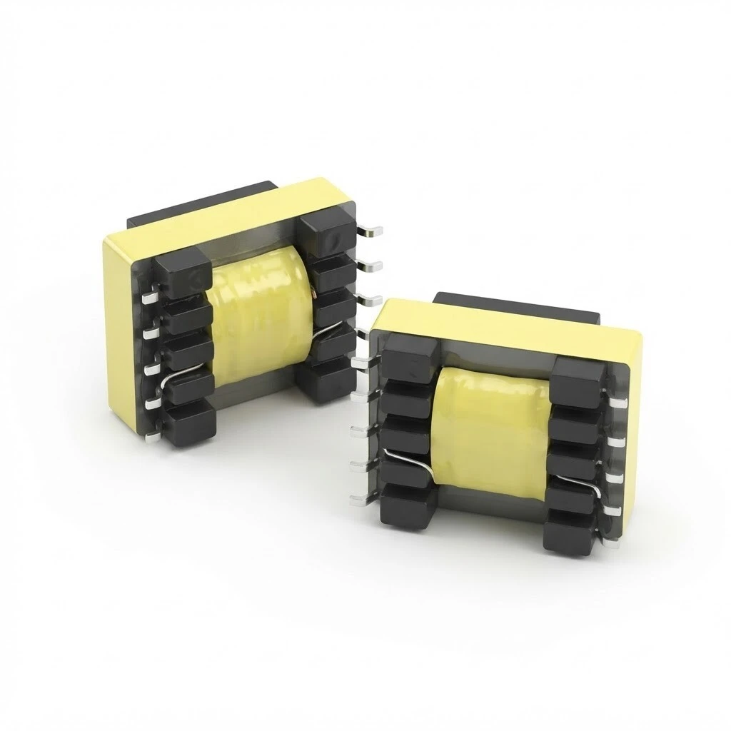
ZXY-ED12.6-20H SMD Audio Isolation Transformer, Permalloy Core, 100 Hz - 20 kHz, 1:1 Turns Ratio, 20 H Inductance, 10-Pin SMD, 17.8 x 13.3 x 10.0 mm
ZXY-ED12.6-20H is an SMD audio isolation transformer on a permalloy core: a sealed core in a high-gloss tape wrap, a plastic bobbin carrying the primary on pins 1-5 and the secondary on pins 6-10, and ten formed SMD pins five to a side. 1:1 within ±2%, 20 H minimum at 1 kHz and 0.3 V, 100 Hz to 20 kHz, 1250 V dielectric withstand. Body 10.0 mm high, 17.8 mm long, 13.3 mm wide.
- Turns ratio 1:1 ±2%, primary on pins 1-5 and secondary on pins 6-10
- Permalloy (nickel-iron) core, sealed, in a high-gloss tape wrap
- Primary inductance 20 H minimum at 1 kHz, 0.3 V
- Frequency range 100 Hz to 20 kHz, covering the audio band
- SMD, ten precision-formed pins, five per side, 2.55 mm pitch
- Dielectric withstand 1250 V at 1 mA for 60 s, primary to secondary
1. Product Name
ZXY-ED12.6-20H SMD 10 pin permalloy core audio isolation transformer for signal coupling. Sealed permalloy core in a tape wrap, primary on pins 1-5 and secondary on pins 6-10, ten formed SMD pins, 1:1 turns ratio, 20 H minimum primary inductance, 100 Hz to 20 kHz, body 10.0 mm high by 17.8 mm long by 13.3 mm wide.
Winding arrangement. The schematic shows the two windings as separate coils with the polarity dots at pin 1 and at pin 6, so the winding sense is fixed by the part and not by the assembler. The four ends that appear on it - 1, 5, 6 and 10 - are the four the electrical table tests between.
The two windings share no conductor, only the core. That is the whole function of the part: a signal crosses the barrier as a changing flux, and nothing else does.
2. Feature
Isolation protects the upstream stage. The transformer keeps the output stage of the preceding equipment from being burned out by a fault on the far side of the barrier, which is the first thing an isolating part is bought for.
AC mains-frequency interference removed. The interference that travels along a shared conductor is blocked at the barrier, so it does not arrive at the next stage as hum.
100 Hz to 20 kHz range. Covers the audio band from the bottom of the speech range to the top of hearing, which is what a coupling stage in a console or a modem line has to pass.
Common-ground hum solved. Breaks the loop formed when the same signal is earthed at two points, which is the usual source of continuous hum in a rack of separately powered units.
Interference reduced in both wirings. Balanced and unbalanced transmission both see less pickup of external interference, so the same part can be used whichever scheme the board is drawn in.
Both units are the same build seen from the two faces that matter at assembly: the sealed core and the pin comb on the left, the coil face inside the tape wrap on the right. The 1:1 ratio and the 20 H primary are properties of that winding and that core together, which is why the part is bought as one piece rather than as a core and a coil.
3. Advantage
Small package, high inductance. A 20 H winding in a surface-mount body of 10.0 mm by 17.8 mm by 13.3 mm, which is the point of the permalloy core: the inductance comes from the core, not from the size.
Permalloy core with a sealed finish. A nickel-iron core in a high-gloss tape wrap, so the winding is covered and the core faces are held in alignment.
Formed SMD pins. The ten pins are formed for surface mounting, which keeps the part inside the reflow process instead of adding a hand-soldering step.
Robust bobbin with core alignment. The plastic bobbin locates the core halves rather than relying on the tape to hold them, which is what keeps the inductance repeatable from unit to unit.
Customised design available. Windings can be built to a customer specification where the standard 20 H part is not the right fit.
Factory-direct supply. Standard parts ship from stock, which keeps the lead time off the critical path.
The callouts pick out the three things that decide whether the part works in a reflow line: the core is seated and held by the bobbin rather than by the tape, the tape wrap is continuous over the winding, and the pins are formed to lie flat on the pad. The top view shows the pin comb at the same time - five leads a side on 2.55 mm centres, with the body between them a shade under 13.3 mm wide.
4. Application
Communication equipment and high-speed modems. Line coupling where the modem side and the line side must stay isolated from each other.
Telephone coupling and analogue modems. The 100 Hz to 20 kHz band covers the voice channel and the modulated carriers above it.
Mixing console signal isolation output. An isolated output that does not tie the console ground to the ground of whatever it feeds.
Multi-channel signal isolation output. One part per channel where several isolated outputs leave the same board.
In both views the part sits between the two halves of the circuit rather than at its edge, which is where an isolating transformer belongs: the stage on one side of it and the stage on the other have no conductor in common once it is in place. The 10.0 mm height is the figure to check against whatever sits beside it - the case clears the small parts around it, but nothing can be stacked over it.
5. Application Specifications
The specification below is the data declared for this model: product data, the electrical table at 25 °C, the outline and pin dimensions, and the pin assignment with its winding polarity.
5.1 Product specification
| Item | Value |
|---|---|
| Model / part no. | ZXY-ED12.6-20H |
| Product type | Permalloy-core audio isolation transformer |
| Package | SMD, surface mount, 10 leads, 5 per side |
| Frequency range | 100 Hz - 20 kHz |
| Primary inductance | 20 H min at 1 kHz, 0.3 V |
| Turns ratio, primary to secondary | 1:1 ±2% |
| Dielectric withstand, primary to secondary | 1250 V, 1 mA, 60 s |
| Overall dimensions, H x L x W | 10.0 x 17.8 x 13.3 mm |
| Core | Permalloy (nickel-iron), sealed, high-gloss tape wrap |
| Bobbin | Plastic, with precise core alignment |
| Terminals | Precision-formed SMD pins |
| Windings | Primary 1-5, secondary 6-10 |
| Reference temperature | 25 °C |
| Design service | Customised designs available |
5.2 Electrical specification, 25 °C
Inductance is measured at 1 kHz with a 0.3 V test signal as a minimum; DC resistance carries a tolerance of ±15%; the turns ratio is measured at 10 kHz with 1 V and holds ±2%; dielectric withstand is 1250 V with a 1 mA leakage limit held for 60 s.
| No. | Test item | Test terminal | Limit | Test condition |
|---|---|---|---|---|
| 1 | Inductance | 1-5 = 6-10 | 20 H min | 1 kHz, 0.3 V |
| 2 | DCR | 1-5 | 629 Ω ±15% | 25 °C |
| 2 | DCR | 6-10 | 737 Ω ±15% | 25 °C |
| 3 | Turns ratio, primary to secondary | 1-5 = 6-10 | 1:1 ±2% | 10 kHz, 1 V |
| 4 | Dielectric withstand, primary to secondary | 1,5 - 6,10 | 1250 V | 1 mA, 60 s |
5.3 Outline and pin dimensions
| Parameter | Specification |
|---|---|
| Overall height, H | 10.0 mm |
| Overall length, L | 17.8 mm |
| Overall width, W | 13.3 mm |
| Pin spacing | 2.55 mm on the footprint drawing |
5.4 Pin assignment and winding polarity
| Pin | Winding | Marking |
|---|---|---|
| 1 | Primary | Winding end, polarity dot |
| 2 - 4 | Not stated | Purpose not declared in the source |
| 5 | Primary | Winding end, used as the dielectric test point |
| 6 | Secondary | Winding end, polarity dot |
| 7 - 9 | Not stated | Purpose not declared in the source |
| 10 | Secondary | Winding end, used as the dielectric test point |
Primary winding on pins 1-5, secondary on pins 6-10, with the polarity dot at the start of each: pin 1 for the primary and pin 6 for the secondary. The dielectric test is applied between pins 1 and 5 together against pins 6 and 10 together, which is the pair of groups the table calls 1,5 - 6,10.
6. Quality & Testing Assurance
Every parameter is measured at 25 °C ambient. The test items are the inductance, the DC resistance of both windings, the turns ratio and the primary-to-secondary dielectric withstand, each against the limit in the table below.
| Test item | Specification | Condition |
|---|---|---|
| Inductance | 20 H minimum on both windings | 1 kHz, 0.3 V |
| DC resistance, pins 1-5 | 629 Ω, tolerance ±15% | 25 °C |
| DC resistance, pins 6-10 | 737 Ω, tolerance ±15% | 25 °C |
| Turns ratio, primary to secondary | 1:1, tolerance ±2% | 10 kHz, 1 V |
| Dielectric withstand, primary to secondary | 1250 V between pins 1, 5 and pins 6, 10 | 1 mA, 60 s |
The dielectric test sits between the primary pins 1 and 5 and the secondary pins 6 and 10, held at 1250 V with the leakage current limited to 1 mA for 60 s. It is the test that stands behind the isolation the part is bought for, and the one to repeat if a batch is ever in doubt.
Brand / manufacturer: ZXY, Shenzhen Zhixiangyuan Electronics Co., Ltd. http://www.zxycoil.com