
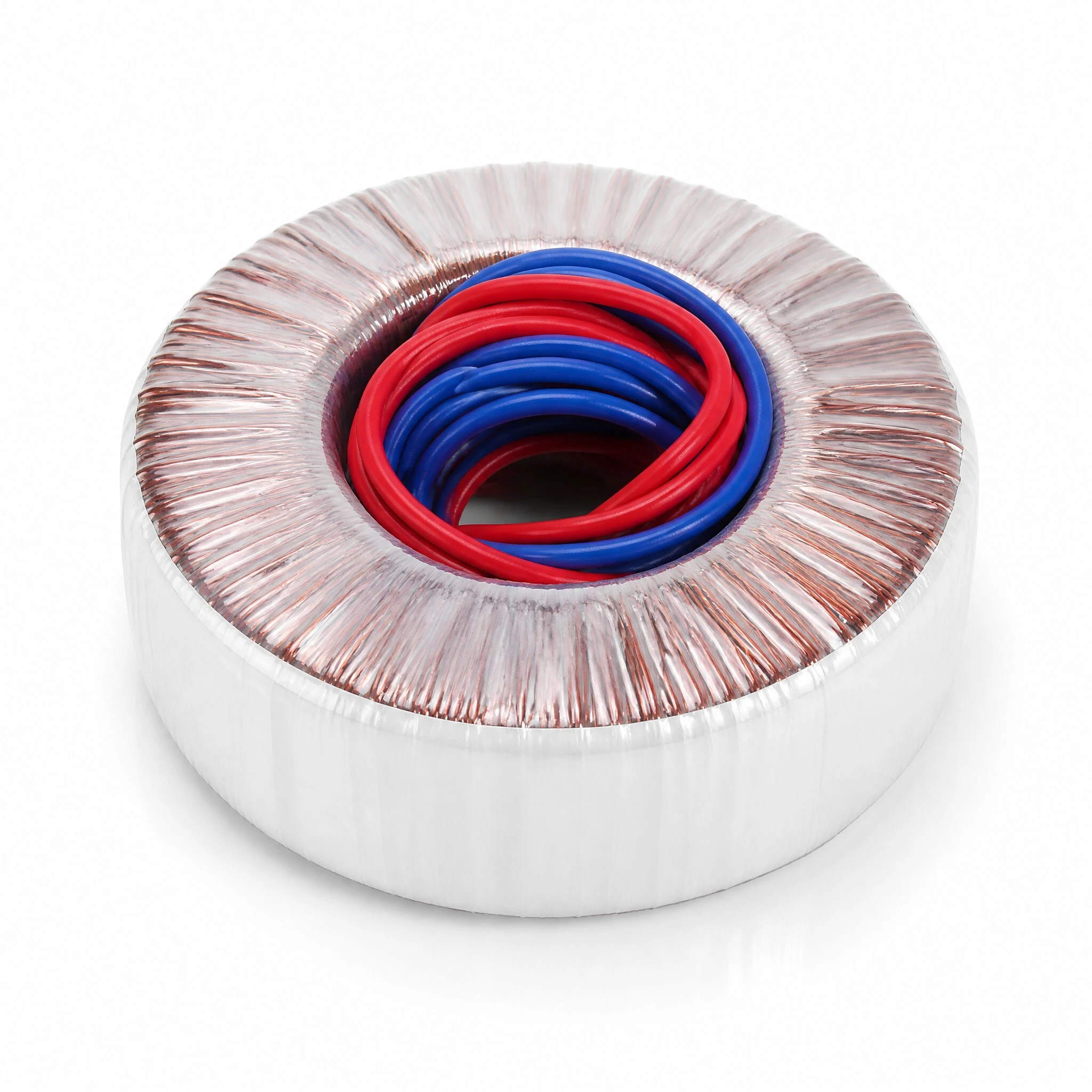
Toroidal Power Transformer TT Series, 20 VA to 1500 VA, 50/60 Hz, 220 V Primary, Custom Secondary, Low Noise
A toroid is chosen when the transformer has to sit close to the signal. The core is a continuous ring of grain-oriented silicon steel with no gap and no laminated stack, so the flux stays inside the ring, the stray field around it is small and there is nothing to buzz at twice the mains frequency. That is why the same family appears in audio chassis and in medical and instrumentation supplies. The TT range covers 20 VA to 1500 VA at 50 Hz or 60 Hz, with the secondary wound to the order, and the supplier publishes a loss and current figure for every rating rather than a single headline number.
- TT series toroidal power transformer, 20 VA to 1500 VA, 50 Hz or 60 Hz.
- Grain-oriented silicon steel ring core, wound with copper wire, no air gap.
- Primary 220 V on two red leads, secondary on two blue leads and made to order.
- No-load iron loss from below 0.9 W at 20 W to below 20 W at 1500 W.
- Hi-pot DC 2500 V primary to secondary and insulation resistance 500 megohm or more on every rating.
- The range shot is a 24 V family, 50 VA at 2.1 A through 1500 VA at 62.5 A.
- Outline, bore, height, lead length, weight and price are absent from the source and left open.
1. Product Name
TT is the series name, not one part. The material covers a toroidal power transformer built on a grain-oriented silicon steel ring core, wound with copper wire, from 20 VA to 1500 VA at 50 Hz or 60 Hz, with a 220 V primary on two red leads and a secondary on two blue leads. Because the secondary is wound to the order, the VA rating is the only quantity that stays fixed across the range; the voltage and the current that go with it change with every build.
The labels follow a pattern: TT, the rating in volt-amperes, the primary voltage, then the secondary voltage. TT1000-220-24 is the 1000 VA build with a 220 V primary and a 24 V secondary, and TT50-220-24 is the same construction at 50 VA. Treat that as the pattern the labels show rather than a published coding rule, and quote the full model when ordering.
2. Core and Construction
The core is a strip of grain-oriented silicon steel wound into a ring and bonded, so the flux path is a closed circle with no gap and the grain runs along the direction the flux travels. That does three things a laminated stack cannot: it removes the air gap that a cut core needs, it keeps the field inside the ring so very little leaks out around the part, and it removes the loose stack that buzzes at twice the mains frequency. The supplier panel names grain-oriented silicon steel and pure copper wire; it does not name the grade of either.
The windings are distributed around the whole ring rather than bunched on one leg, which is what shares the copper over the full circumference and shortens the mean turn. Each winding is brought out as a pair of insulated leads, sleeved where it leaves the coil, and the finished toroid is wrapped first in white tape and then in clear film before it is bolted to its base. The copper is visible through the film between the outer wrap and the core, which is what the close-up shows.
3. Winding and Leads
Two leads come out for the primary and two for the secondary. On the 150 VA unit the label reads input 0 V - 220 V against the red pair and output 0 V - 60 V against the blue pair, both at 50 Hz or 60 Hz; the 300 VA unit is the same arrangement at 0 V - 66 V. Red is the primary and blue is the secondary throughout the range, and the leads are sleeved at the exit rather than terminated, so no connector, tag or ferrule is part of the part as shipped.
4. Mounting
The toroid sits on a black painted steel base plate that is larger than the coil, with a mounting hole at each corner, and it is held down through the centre by a bolt, a nut and a washer stack that passes through the bore. That centre fixing is what keeps the core compressed and stops the part walking; the corner holes take the plate to the chassis floor or to a side panel. Plate size, hole diameter, bolt thread and the height of the stack are not given in the material.
5. Electrical Range
The table is the offering, one row per rating, and the only place the winding is described. Every row is tested primary to secondary at DC 2500 V and quoted at 500 megohm or more, so those two columns are stated once instead of fifteen times. No-load iron loss is the only loss figure published: no efficiency, regulation, temperature rise or leakage inductance appears.
5.1 Ratings as published
| Power | No-load secondary | Full-load current | Iron loss |
|---|---|---|---|
| 20 W | AC12.0V +/-2% | 1.66 A | <0.9 W |
| 40 W | AC12.5V +/-2% | 3.3 A | <2.0 W |
| 50 W [230 V] | AC5-0-5V +/-2% | 5.0 A | <2.0 W |
| 70 W [230 V] | AC14.5V +/-2% | 5.0 A | <3.0 W |
| 90 W | AC28+9+16V, sign doubled as printed | 2.1+1.7+1 A | <3.0 W |
| 120 W | AC20-20-80-100V+1V +/-2% | 6 A | <3.0 W |
| 150 W | AC22V +/-2% | 6.8 A | <3.0 W |
| 200 W | AC12V x 2, +/-2% | 8.4 A | <4.0 W |
| 240 W | AC24V +/-2% | 10 A | <4.0 W |
| 300 W | AC24.5V +/-2% | 12.5 A | <5.0 W |
| 400 W | AC70.5V +/-2% | 5.7 A | <6.0 W |
| 500 W | AC36V +/-2% | 13.9 A | <4.5 W |
| 1000 W [240 V] | AC36.5V +/-2% | 27.5 A | <10 W |
| 1200 W | AC45+36V +/-2% | 13.3+16.6 A | <12 W |
| 1500 W [415 V] | AC48V +/-2% | 31.2 A | <20 W |
5.2 The two labelled units
Two units are photographed with labels legible. Both take 220 V into the red pair; the secondaries are 60 V and 66 V, neither matching the 24 V family shot or the table row for the same rating. The rating matches, the winding does not.
6. Model Range
The range shot is one family at one secondary voltage: eleven legible labels, all 24 V, from 50 VA at 2.1 A to 1500 VA at 62.5 A. Each current is the rating divided by 24 V, which is what confirms the family rather than any single label. The smallest unit carries a TT-20 label too small to read at this resolution and is not tabulated. The table gives a different secondary for each rating: the two panels are the same platform at two sets of windings.
6.1 The 24 V family
| Model | Rating | Secondary | Current |
|---|---|---|---|
| TT-50 | 50 VA | 24 V | 2.1 A |
| TT-100 | 100 VA | 24 V | 4.2 A |
| TT-150 | 150 VA | 24 V | 6.3 A |
| TT-200 | 200 VA | 24 V | 8.3 A |
| TT-300 | 300 VA | 24 V | 12.5 A |
| TT-400 | 400 VA | 24 V | 16.7 A |
| TT-500 | 500 VA | 24 V | 20.8 A |
| TT-600 | 600 VA | 24 V | 25 A |
| TT-800 | 800 VA | 24 V | 33.3 A |
| TT-1000 | 1000 VA | 24 V | 41.7 A |
| TT-1500 | 1500 VA | 24 V | 62.5 A |
7. Quality and Compliance
The compliance panel shows the CE, UL, RoHS and CCC marks under the line compliant with global safety standards. The 150 VA label also carries the double-square mark and a warning triangle. No certificate number, standards reference or test report is reproduced with any of them, so they are reported here as marks and declarations rather than as certified facts. The one test that is specified is the hi-pot, and it is a DC test at 2500 V, not an AC test.
| Item | Statement | Note |
|---|---|---|
| Hi-pot | DC 2500 V, primary to secondary | Every rating, AC not DC |
| Insulation resistance | 500 megohm or more | Same condition as the hi-pot |
| CE | Mark shown | No certificate number |
| UL | Mark shown | No certificate number |
| RoHS | Mark shown | No report reproduced |
| CCC | Mark shown | No certificate number |
8. Feature
Ring core, no gap. The strip is wound closed, so there is no air gap in the flux path and no magnetising current to spend on one.
Low stray field. The field stays inside the ring, which is why a toroid can sit next to a signal stage that a laminated part would hum into.
No stack to buzz. A wound ring has no loose laminations, so the mechanical noise at twice the mains frequency is not there to begin with.
One platform, 20 VA to 1500 VA. The same construction and the same mounting scheme carry from the smallest unit to the 1500 W rating.
Secondary wound to order. Voltage, current, taps and the number of secondaries are set by the order, which is why the same VA appears at several voltages.
9. Advantage
Iron loss is on the sheet, not implied. Most catalogue pages quote a VA figure and stop there. Here every rating carries its own no-load iron loss, which is the number that decides how hot a sealed enclosure runs.
Insulation is specified at both ends. A DC 2500 V hi-pot and an insulation resistance of 500 megohm or more apply to every row, so the barrier is a stated requirement rather than a note about good practice.
A family, not a single size. Fifteen ratings in the table and eleven in the range shot cover a chassis design that grows without changing the mounting or the lead colour code.
Mounting arrives fitted. The base plate and centre bolt come with the part, so the chassis needs a flat surface and four holes, not a bracket designed around the transformer.
Custom winding with a fixed core. Because only the winding changes between builds, a second voltage is a winding change on a known core, which is a shorter path than a new design.
10. Specifications
Values are transcribed from the supplier panels. Where a figure is absent the cell reads Not stated; where the material contradicts itself the contradiction is named rather than resolved.
10.1 Summary
| Item | Specification | Note |
|---|---|---|
| Product | TT series toroidal power transformer | Series, wound to order |
| Winding | Copper wire, distributed around the ring | Wire grade not stated |
| Rating | 20 VA to 1500 VA | Fifteen ratings in the table |
| Primary | 220 V, two red leads | Four rows list another input |
| Secondary | Two blue leads, wound to order | Voltage varies by build |
| Frequency | 50 Hz / 60 Hz | Every row |
| Insulation | Hi-pot DC 2500 V, 500 megohm or more | Primary to secondary |
| Mounting | Steel base plate, centre through-bolt | Plate size not stated |
| Weight | Not stated | No figure anywhere in the material |
10.2 Mechanical
| Item | Specification | Note |
|---|---|---|
| Core | Wound silicon steel ring | Grain-oriented, no gap |
| Outer wrap | White tape under clear film | Material grade not stated |
| Leads | Red primary pair, blue secondary pair | Sleeved at the exit |
| Termination | None fitted | Leads arrive cut |
| Base plate | Painted steel, four corner holes | Size and hole diameter not stated |
| Centre fixing | Bolt, nut and washer through the bore | Thread not stated |
| Lead length | Not stated | Shown as a dimension line, no value |
| Outline | Not stated | OD, ID and H are symbols only |
11. Application
The uses below are the categories the supplier quotes for the range, with a short note on why a toroid suits each. They describe where the family is sold, not a qualification of any one build.
Audio amplifiers. The photograph in this page is a toroid inside an amplifier beside the reservoir capacitors, which is the classic use: the low stray field keeps hum out of the signal path.
Medical supplies. Isolated supplies where the hi-pot result has to be on record and the enclosure is often sealed, so iron loss matters more than efficiency.
Industrial power. Control and drive supplies that need a compact isolated rail and a mounting plate rather than a bracket.
Renewable and inverter stages. Auxiliary and gate-drive supplies inside inverter and converter cabinets.
Instrumentation and test equipment. Bench and rack supplies where the transformer sits close to low-level circuitry.
12. Ordering
Send the winding, not just a VA figure. A usable enquiry gives the rating, the primary voltage, the secondary voltage or the list of secondaries, the frequency, the lead length you need, whether the base plate and centre bolt are wanted, and the quantity per order and per delivery. With those the core, the wire, the turns and the plate are fixed and the price follows. If the chassis already exists, send the outline you have to fit and the mounting hole pattern so the plate is checked before the winding starts.
On compliance: the panels show the CE, UL, RoHS and CCC marks and state compliance with global safety standards. No certificate number, standards reference or test report appears, so these are marks and declarations rather than certified facts. The one specified test is the DC 2500 V hi-pot at an insulation resistance of 500 megohm or more. If your equipment has to meet a named standard, ask for the certificate and the report before design-in.
Brand / manufacturer: ZXY, Shenzhen Zhixiangyuan Electronics Co., Ltd. http://www.zxycoil.com