loading

ZXY: 26 Years of Excellence as a Leading Transformer and Inductor Manufacturer ・ One-Stop Solutions

ZXY2207 Permalloy Audio Isolation Transformer, 600:600 / 600:600 Dual / 10K:10K / 600:10K / 10K:600, Ground Loop Noise Isolator, 6-Pin PCB Mount 1
ZXY2207 Permalloy Audio Isolation Transformer, 600:600 / 600:600 Dual / 10K:10K / 600:10K / 10K:600, Ground Loop Noise Isolator, 6-Pin PCB Mount 2
ZXY2207 Permalloy Audio Isolation Transformer, 600:600 / 600:600 Dual / 10K:10K / 600:10K / 10K:600, Ground Loop Noise Isolator, 6-Pin PCB Mount 3
ZXY2207 Permalloy Audio Isolation Transformer, 600:600 / 600:600 Dual / 10K:10K / 600:10K / 10K:600, Ground Loop Noise Isolator, 6-Pin PCB Mount 4
ZXY2207 Permalloy Audio Isolation Transformer, 600:600 / 600:600 Dual / 10K:10K / 600:10K / 10K:600, Ground Loop Noise Isolator, 6-Pin PCB Mount 5
ZXY2207 Permalloy Audio Isolation Transformer, 600:600 / 600:600 Dual / 10K:10K / 600:10K / 10K:600, Ground Loop Noise Isolator, 6-Pin PCB Mount 6
ZXY2207 Permalloy Audio Isolation Transformer, 600:600 / 600:600 Dual / 10K:10K / 600:10K / 10K:600, Ground Loop Noise Isolator, 6-Pin PCB Mount 7
ZXY2207 Permalloy Audio Isolation Transformer, 600:600 / 600:600 Dual / 10K:10K / 600:10K / 10K:600, Ground Loop Noise Isolator, 6-Pin PCB Mount 8
ZXY2207 Permalloy Audio Isolation Transformer, 600:600 / 600:600 Dual / 10K:10K / 600:10K / 10K:600, Ground Loop Noise Isolator, 6-Pin PCB Mount 9
ZXY2207 Permalloy Audio Isolation Transformer, 600:600 / 600:600 Dual / 10K:10K / 600:10K / 10K:600, Ground Loop Noise Isolator, 6-Pin PCB Mount 10
ZXY2207 Permalloy Audio Isolation Transformer, 600:600 / 600:600 Dual / 10K:10K / 600:10K / 10K:600, Ground Loop Noise Isolator, 6-Pin PCB Mount 1
ZXY2207 Permalloy Audio Isolation Transformer, 600:600 / 600:600 Dual / 10K:10K / 600:10K / 10K:600, Ground Loop Noise Isolator, 6-Pin PCB Mount 2
ZXY2207 Permalloy Audio Isolation Transformer, 600:600 / 600:600 Dual / 10K:10K / 600:10K / 10K:600, Ground Loop Noise Isolator, 6-Pin PCB Mount 3
ZXY2207 Permalloy Audio Isolation Transformer, 600:600 / 600:600 Dual / 10K:10K / 600:10K / 10K:600, Ground Loop Noise Isolator, 6-Pin PCB Mount 4
ZXY2207 Permalloy Audio Isolation Transformer, 600:600 / 600:600 Dual / 10K:10K / 600:10K / 10K:600, Ground Loop Noise Isolator, 6-Pin PCB Mount 5
ZXY2207 Permalloy Audio Isolation Transformer, 600:600 / 600:600 Dual / 10K:10K / 600:10K / 10K:600, Ground Loop Noise Isolator, 6-Pin PCB Mount 6
ZXY2207 Permalloy Audio Isolation Transformer, 600:600 / 600:600 Dual / 10K:10K / 600:10K / 10K:600, Ground Loop Noise Isolator, 6-Pin PCB Mount 7
ZXY2207 Permalloy Audio Isolation Transformer, 600:600 / 600:600 Dual / 10K:10K / 600:10K / 10K:600, Ground Loop Noise Isolator, 6-Pin PCB Mount 8
ZXY2207 Permalloy Audio Isolation Transformer, 600:600 / 600:600 Dual / 10K:10K / 600:10K / 10K:600, Ground Loop Noise Isolator, 6-Pin PCB Mount 9
ZXY2207 Permalloy Audio Isolation Transformer, 600:600 / 600:600 Dual / 10K:10K / 600:10K / 10K:600, Ground Loop Noise Isolator, 6-Pin PCB Mount 10

ZXY2207 Permalloy Audio Isolation Transformer, 600:600 / 600:600 Dual / 10K:10K / 600:10K / 10K:600, Ground Loop Noise Isolator, 6-Pin PCB Mount

Permalloy audio isolation transformer | 600:600 to 10K:10K | 1250 V Hi-Pot | 6-pin PCB mount

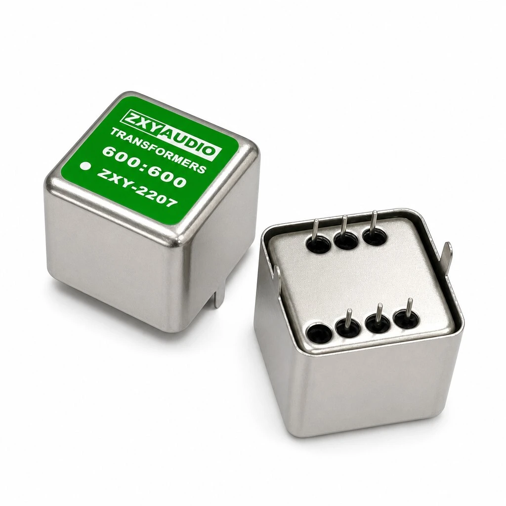
ZXY2207 is a permalloy audio isolation transformer in a shielded metal can, made in five builds from 600:600 to 10K:10K. Ratio held to ±2%, DC resistance to ±15%, dielectric withstand 1250 V AC at 1 mA for 60 s. Six pins on a 4.0 mm grid, footprint 22.0 x 18.3 mm, operating −40 °C to +85 °C. The windings are tightly coupled on a high-permeability core, which is what holds the response flat across the band.

ZXY2207: the case marked 600:600 with the polarity dot, beside a second unit showing the six pins
KEY HIGHLIGHTS
  • 600:600, 600:600 dual, 10K:10K, 600:10K and 10K:600 on one body
  • Turns ratio held to ±2%, DC resistance to ±15% at 25 °C
  • Inductance from 6.0 H on the 600:600 build to 105 H on the 10K:10K
  • Complete permalloy metal shielding enclosure around core and winding
  • Dielectric withstand 1250 V AC at 1 mA for 60 s
  • Six pins, three per side, on a 4.0 mm pitch; 22.0 x 18.3 mm footprint
Pins 2 and 5 are taps, not extra winding ends. The schematic draws three terminals on each side - 1, 2 and 3 on the primary, 4, 5 and 6 on the secondary - with the tap in the middle, and inductance and resistance are both specified across 1-3 and 4-6. The 1+1 : 1+1 build is the one that uses the taps, bringing two 1:1 windings out on each side. The source does not state where along the winding the tap sits, so treat the two halves as a pair of 1:1 windings rather than assuming an electrical centre until the factory confirms it.
5.0
Model:
ZXY2207
Operating Temperature:
−40 °C to +85 °C
Declared Compliance:
RoHS, CE, FCC, ISO 9001
DC Resistance:
30 Ω to 710 Ω, per build
Builds:
600
Dielectric Withstand:
1250 V AC, 1 mA, 60 s
Package:
PCB pin mount, 6 pins, 3 per side
Inductance:
6.0 H to 105 H, per build
Core:
Permalloy, complete metal shielding
Turns Ratio:
1
design customization

    oops...!

    no product data.

    Go to homepage
    THD+N
    below 0.005%
    Relative Humidity
    5% to 95%
    Footprint
    22.0 x 18.3 mm
    Ratio Tolerance
    ±2%
    Builds
    5 builds, see the variant table
    Inductance Test
    100 Hz, 0.3 V
    DCR Tolerance
    ±15%
    Dielectric Withstand
    1250 V AC, 1 mA, 60 s
    Storage Temperature
    −45 °C to +125 °C
    Package
    6-pin PCB mount
    Inductance
    6.0 H to 105 H
    Model
    ZXY2207
    DC Resistance
    30 Ω to 710 Ω
    Product Type
    Permalloy audio isolation transformer
    Compliance
    RoHS, CE, FCC, ISO 9001 declared
    Operating Temperature
    −40 °C to +85 °C
    Shielding
    Complete permalloy metal enclosure
    Pin Pitch
    4.0 mm
    Turns Ratio
    1
    Core
    Permalloy, high permeability

    1. Product Name

    ZXY2207 permalloy audio isolation transformer, ground loop noise isolator for DI boxes, tube preamps and line-level audio, in five builds: 600:600, 600:600 dual, 10K:10K, 600:10K and 10K:600. Shielded metal can, six PCB pins on a 4.0 mm grid, footprint 22.0 x 18.3 mm.

    Front elevation: 22.0 mm wide, the green marking carrying the ratio and the model
    Front elevation: 22.0 mm wide, the green marking carrying the ratio and the model

    The can. The marking on the face carries the ratio, the model and the polarity dot, so a populated board can be checked without referring to a drawing. The can itself is the shield: it closes over the core and the winding, and the tab at the base is what the part sits on when it is seated.

    The reason for a metal can rather than a bare bobbin is the application: these parts sit between equipment earthed separately, at levels where a few millivolts of induced hum is audible. Shielding the winding and closing the magnetic path are one piece of metal doing two jobs.

    2. Feature

    High-permeability permalloy core. The core is chosen for permeability rather than for size, which is where the inductance of the higher-ratio builds comes from.

    Noise elimination and ground loop isolation. The two windings share no conductor, so a ground potential difference between two pieces of equipment has no path through the part.

    Ultra-wide and flat frequency response. Coupling close to one keeps the response flat across the band; the low end is set by the primary inductance and the top by the leakage inductance.

    Complete permalloy metal shielding enclosure. The can closes around the core and winding, so external fields reach the windings attenuated rather than directly.

    High Hi-Pot isolation rating. 1250 V AC held at a 1 mA leakage limit for 60 s, between the primary and the secondary.

    Compact PCB pin-mount design. Six pins on a 4.0 mm grid over a 22.0 x 18.3 mm footprint, placed and soldered with the rest of the board.

    Callouts: permalloy shielding over the winding, and the declared CE, RoHS, FCC and ISO 9001 status
    Callouts: permalloy shielding over the winding, and the declared CE, RoHS, FCC and ISO 9001 status

    The two callouts are the two halves of the proposition. On one side, permalloy shielding over the winding - what stops external fields reaching the coil. On the other, the compliance status the specification declares: CE, RoHS, FCC and ISO 9001. The certificate numbers are not given in the source, so ask for them if your file needs them.

    3. Advantage

    100% factory-direct customisation. Windings are built to the customer's ratio and impedance rather than picked from a catalogue, which is why five builds are offered on one body.

    Low total harmonic distortion. THD+N is stated below 0.005%, the figure that decides whether a transformer can sit in a signal path without colouring it audibly.

    High consistency across batches. Ratio is held to ±2% and DC resistance to ±15%, so a replacement part behaves like the one it replaces.

    Global market compliance declared. RoHS, CE, FCC and ISO 9001 are declared for the part; the certificates themselves should be requested if they are needed on file.

    Wide temperature and harsh-environment range. Operating −40 °C to +85 °C, storage −45 °C to +125 °C, 5% to 95% relative humidity.

    The shielded can from the back, with the mounting tab and the pin comb on the near face
    The shielded can from the back, with the mounting tab and the pin comb on the near face
    Pin face square on: six pins, three to a row, in a 4.0 mm grid
    Pin face square on: six pins, three to a row, in a 4.0 mm grid

    The back of the can and the pin face are what a footprint is drawn from: six pins in two rows of three on a 4.0 mm grid, the mounting tab on one side, and no adjustment anywhere. Because the pin rows are symmetric, the orientation of the part on the board is fixed by the polarity dot and not by the pin pattern - fit it the wrong way round and the output is inverted.

    4. Application

    Professional DI boxes and audio isolators. Stage instrument pickup, electric guitar and bass impedance matching, and balanced to unbalanced conversion over long cable runs.

    Tube preamps and hi-fi systems. Input or output coupling for a preamplifier, and the transformer that does balanced conversion and tonal coloration in a valve circuit.

    AV multimedia engineering and commercial display. Isolating a computer or a player from a projector, an LED wall or a stage sound system, where the two are fed from different supplies.

    Broadcast and recording studio consoles. Removing the hum that appears when a console, a workstation, a matrix processor and the reinforcement system sit at different ground potentials.

    Car audio and DSP signal processors. Keeping ignition noise and alternator whine out of the signal path, both of which arrive as a ground-borne difference rather than as audio.

    AV application: player in, isolated out to projector, LED display and sound system
    AV application: player in, isolated out to projector, LED display and sound system
    On the bench beside the audio analyser that sweeps the band and measures distortion
    On the bench beside the audio analyser that sweeps the band and measures distortion
    A single unit on a machined test plate, the can and the tab picked out by the light
    A single unit on a machined test plate, the can and the tab picked out by the light

    The AV diagram is the case the part is bought for most often: a player on one supply feeding a projector, an LED display and a sound system on others. The bench view is the other half of the claim - every unit is swept across the band and its distortion measured before it is packed.

    5. Application Specifications

    The specification below is the data declared for this part: the general data, the electrical table per build, the outline as drawn, and the pin assignment with its taps.

    5.1 Product specification

    ItemValue
    Part numberZXY2207
    Builds600:600, 600:600 (dual), 10K:10K, 600:10K, 10K:600
    Turns ratio1:1, 1+1 : 1+1, 1:1, 1:4, 4:1
    Ratio tolerance±2%
    CorePermalloy, high permeability
    ShieldingComplete permalloy metal enclosure
    WindingCopper, tightly coupled, coupling coefficient close to 1
    PackagePCB pin mount, 6 pins, 3 per side
    Footprint22.0 x 18.3 mm
    Pin pitch4.0 mm
    Dielectric withstand1250 V AC, 1 mA, 60 s
    Operating temperature−40 °C to +85 °C
    Storage temperature−45 °C to +125 °C
    Relative humidity5% to 95%
    Reference temperature25 °C
    Declared complianceRoHS, CE, FCC, ISO 9001
    OEM / ODMAvailable, sample lead time 7-10 days

    5.2 Electrical specification, five builds, 25 °C

    Inductance is a minimum measured at 100 Hz with a 0.3 V signal across pins 1-3 and 4-6; DC resistance carries ±15% at 25 °C; the ratio carries ±2%; dielectric withstand is 1250 V AC at a 1 mA leakage limit for 60 s.

    Part No.RatioTol.LS 1-3LS 4-6DCR 1-3DCR 4-6Hi-Pot
    ZXY2207-600:6001:1±2%6.0 H6.0 H30 Ω30 Ω1250 V AC
    ZXY2207-600:600 (dual)1+1 : 1+1±2%14.0 H14.0 H75 Ω75 Ω1250 V AC
    ZXY2207-10K:10K1:1±2%105 H105 H600 Ω600 Ω1250 V AC
    ZXY2207-600:10K1:4±2%8.0 H110 H37 Ω710 Ω1250 V AC
    ZXY2207-10K:6004:1±2%100 H6.0 H558 Ω40 Ω1250 V AC
    The five builds share the case, the pinout and the 1250 V isolation, and differ in winding. 600:600 is the 1:1 line-level part; 600:600 (dual) is 1+1 : 1+1, the same ratio made as two windings per side; 10K:10K is the 1:1 high-impedance version and needs 105 H to hold its low end; 600:10K is 1:4 and 10K:600 is 4:1, the two directions of the same impedance step. A build is not interchangeable with its neighbour: picking 600:10K where the circuit wants 10K:600 inverts the impedance transformation as well as the ratio.

    5.3 Outline dimensions

    ParameterDimension
    Body width, as drawn0.866 in = 22.0 mm
    Body length, as drawn0.721 in = 18.3 mm
    Third dimension, as drawn0.285 in (7.24 mm converted)
    Pin pitch0.157 in = 4.0 mm
    Dimension at the base, as drawn0.079 in (2.01 mm converted)
    Pin hole diameter, as drawn0.027 in (0.69 mm converted)
    Body per the callout artwork22 x 22 x 18.3 mm
    Standard footprint0.866 in
    Outline and schematic: 22.0 x 18.3 mm body, and the 1:1 winding with pins 1-3 against 4-6
    Outline and schematic: 22.0 x 18.3 mm body, and the 1:1 winding with pins 1-3 against 4-6
    The outline appears in two forms that do not line up exactly. The dimension drawing is in inches: 0.866 in across, 0.721 in the other way, a third figure of 0.285 in, a pin pitch of 0.157 in, 0.079 in at the base and a pin hole of 0.027 in. The callout artwork gives the body as 22 x 22 x 18.3 mm. They agree on 22.0 mm, 18.3 mm and the 4.0 mm pitch but not on the third dimension, so confirm the height on a sample before committing a footprint. Only the inch figures are printed; the other metric values here are conversions.

    5.4 Pin assignment and winding polarity

    PinWindingMarking
    1Primary winding, end AWinding start, polarity dot; measured with 3 as LS 1-3
    2Primary tapBetween 1 and 3; used by the 1+1 : 1+1 build
    3Primary winding, end BMeasured with 1 as LS 1-3
    4Secondary winding, end AMeasured with 6 as LS 4-6
    5Secondary tapBetween 4 and 6; used by the 1+1 : 1+1 build
    6Secondary winding, end BWinding start, polarity dot; measured with 4 as LS 4-6
    600:600 audio matching, balanced 1:1 transfer, on a 4.0 mm (0.157 in) pin pitch
    600:600 audio matching, balanced 1:1 transfer, on a 4.0 mm (0.157 in) pin pitch
    Pins 2 and 5 are taps, not extra winding ends. The schematic draws three terminals on each side - 1, 2 and 3 on the primary, 4, 5 and 6 on the secondary - with the tap in the middle, and inductance and resistance are both specified across 1-3 and 4-6. The 1+1 : 1+1 build is the one that uses the taps, bringing two 1:1 windings out on each side. The source does not state where along the winding the tap sits, so treat the two halves as a pair of 1:1 windings rather than assuming an electrical centre until the factory confirms it.

    6. Quality & Testing Assurance

    Every unit is tested before packing, not sampled. The test items are the turns ratio and polarity, the inductance of both windings, the DC resistance of both, the 1250 V Hi-Pot between primary and secondary, and an audio band sweep with distortion measurement.

    Test itemSpecificationCondition
    Turns ratio and polarityEvery unit, ±2% against the build25 °C
    Inductance, pins 1-3 and 4-6Minimum per build, in the table above100 Hz, 0.3 V
    DC resistance, pins 1-3 and 4-6Per build, tolerance ±15%25 °C
    Dielectric withstand, primary to secondary1250 V AC1 mA, 60 s
    Audio band sweep and THDEvery unit—
    Final inspection100% factory testing before packing—

    Packing is a custom foam grid inside a heavy-duty export carton, so the cans arrive with their pins straight. OEM and ODM work is available, with a sample lead time of 7-10 days.

    This page quotes the construction, electrical and test data the specification declares, at 25 °C for the electrical values. The temperature and humidity ranges come from the datasheet; the product text gives no figures for them. The specification declares RoHS, CE, FCC and ISO 9001 compliance but gives no certificate number for any of them, so the declaration is reproduced as made and the certificates should be requested if they are needed on file. No weight, MOQ or price is stated, so none is given here. The case is marked ZXY-2207 while the ordering codes are ZXY2207-600:600 and so on - same part, two forms of the model name. The frequency response is described as uniform across the operating band without figures, so no band edges are claimed; THD+N below 0.005% is quoted as the specification states it.

    Brand / manufacturer: ZXY, Shenzhen Zhixiangyuan Electronics Co., Ltd. http://www.zxycoil.com

    Message Form
    We Can Help You Solve Any Problem 
    Just leave your email or phone number in the contact form so we can send you a free quote for our wide range of designs!
    Related Products
    Huizhou Company Address
    Zhixiangyuan Technology Co., Ltd., 5th Floor, Building 4, Xinghe Industrial Park, Zhongkai High tech Zone, Huicheng District, Huizhou City, Guangdong Province
    Contact Us
    Contact Person: Rhea Chen
    Tel/WhatsApp: +86 13554723725
    Fax: 86-0755-23779620
    Shenzhen Company Address
    Room 202, Yingfei Haocheng Science and Technology Park, Guansheng 5th Road, Luhu Community, Guanhu Street, Longhua District, Shenzhen City, Guangdong Province, China
    Customer service
    detect