
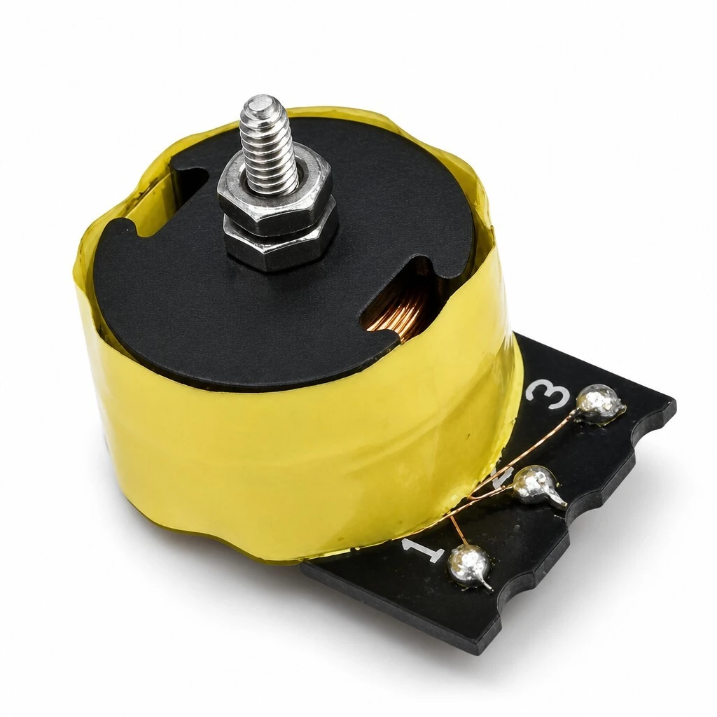
ZXY-G14 Audio Transformer, 420 mH G14 Pot Core PCB Mount Transformer for Audio Circuits
ZXY-G14 is an audio transformer on a G14 pot core in XP95 ferrite, wound in 0.12 mm self-bonding enamel wire and bonded with 316 anaerobic adhesive. Inductance at least 420 mH at 10 kHz and 1 V on pins 2-3, DC resistance 19 Ω ±10% at 25 °C. Three 0.7 mm pins on a 3.5 mm pitch with a 7.0 mm row, a central M2 stud for chassis fixing, and a body of 16.3 mm diameter by 13.8 mm high. Part number G2610.
- G14 pot core in XP95 ferrite, one set per unit, closed magnetic circuit
- Inductance at least 420 mH at 10 kHz and 1 V across pins 2-3
- DC resistance 19 Ω ±10% at 25 °C on the same pair
- 0.12 mm self-bonding enamel wire, core and base bonded with 316 adhesive
- Three 0.7 mm pins, 3.5 mm pitch, 7.0 mm row, base BASS-1673
- Body 16.3 mm diameter by 13.8 mm high, central M2 x 16 stud with nut
1. Product Name
ZXY-G14 audio transformer, part number G2610: a G14 pot core in XP95 ferrite, wound in 0.12 mm self-bonding enamel wire, bonded with 316 anaerobic adhesive, on a BASS-1673 base with three 0.7 mm pins and a central M2 stud. 420 mH at 10 kHz and 1 V on pins 2-3, 19 Ω ±10% at 25 °C, 16.3 mm diameter by 13.8 mm high.
The marking. The model is printed on the body, so a populated board can be identified without a drawing. The stud sits on the axis of the pot core, which is the only place it can sit without cutting into the magnetic path.
Seen from the front the part is a cylinder standing on a flat base, three pins below and the stud above. The height is set by the core stack, not by a bobbin standing off the board, which is why 13.8 mm buys a 420 mH winding that a conventional open frame would need much more room for.
2. Construction & Materials
The base. BASS-1673 carries the three terminals, numbered 1, 2 and 3 in the moulding, and the head of the M2 screw sits between them. The numbering is what the electrical table refers to: the winding is specified across pins 2 and 3.
The base is also the datum for the footprint. Its outline fixes the 3.5 mm pitch and the 7.0 mm row, so a board drawn for this base will accept any winding built on it, which is what makes the custom option practical rather than a new layout each time.
The core. Two XP95 ferrite halves meet at a centre boss and enclose the winding, with only the slot the leads pass through left open. The yellow tape over the assembly is what holds the halves together while the adhesive cures and protects the winding afterwards.
A pot core is chosen over an RM or an E core here for one reason: the closed shape. Almost all of the flux stays in the ferrite, so the part neither radiates into a nearby high-impedance node nor picks up what a neighbouring component radiates. That property, not the inductance alone, is what an audio circuit is buying.
3. Feature
G14 pot core in XP95 ferrite. The pot core encloses the winding in a closed magnetic circuit, so almost all of the flux stays inside the ferrite and very little escapes to induce hum in a neighbouring circuit. XP95 is the grade supplied by Xintong Magnetoelectric, one set per unit.
0.12 mm self-bonding enamel wire. The wire is hot-air bonded as it is wound, so the turns stay where they were put and the winding geometry does not move between units. That is what makes the inductance repeatable rather than a tolerance band.
Bonded, not clamped. Core, coil and base are held together with 316 anaerobic adhesive. There is no clip to work loose under vibration and no air gap that can change with handling.
Three pins on a standard pitch. Three pins of 0.7 mm on a 3.5 mm pitch with a 7.0 mm row drop into a footprint that already exists on most audio boards, so the part needs no bracket of its own.
Central M2 fixing. An M2 x 16 round-head screw through the middle of the pot core, with an M2 x 2 nut, ties the part to a chassis or a bracket where the board alone would not hold it.
4. Advantage
Small envelope. At 16.3 mm diameter and 13.8 mm high the part frees board space in dense audio circuits, and the height is set by the pot core rather than by a bobbin standing off the board.
Repeatable inductance. Because the winding is bonded and the core is bonded to the base, the geometry that sets 420 mH is fixed at assembly. Units do not drift apart in value as they are handled or as the equipment warms.
Drops into an existing footprint. The 3.5 mm pitch and 7.0 mm row are the reason the part can replace a transformer already designed in, without a board revision.
Fixing where vibration matters. The central stud takes the load off the solder joints when the assembly is mounted on a chassis that moves, which is the case in most audio equipment that is not a desktop box.
Built to your drawing. Winding, inductance value, base and pin-out can be adapted, so the same core and construction serve a range of audio designs rather than one catalogue value.
5. Application
Audio signal circuits. Where a compact 420 mH inductive component is needed in the signal path, the pot core gives the inductance without the stray field of an open bobbin.
Low-frequency filtering and coupling. Positions on a PCB assembly that filter or couple at audio frequency, on pins 2-3 of the base.
Custom projects. Built to a customer drawing or a sample, for equipment where the standard winding is not the right value.
Chassis-mounted audio modules. Where board space and mounting stability both matter, the central stud carries the part to the chassis while the pins hold it to the board.
On the board the terminals sit in through-holes and the part stands clear, so the stud is reachable from above once the board is populated. That ordering matters on an assembly where the transformer is added before the chassis is closed.
6. Application Specifications
The data below is the approval specification for G2610, edition A/0 dated 2026-08-28, reproduced as declared.
6.1 Product specification
| Parameter | Specification | Test condition / note |
|---|---|---|
| Model / Part No. | ZXY-G14 / G2610 | — |
| Core | G14 pot core, XP95 ferrite, 1 set | Xintong Magnetoelectric |
| Winding wire | 0.12 mm self-bonding enamel wire | Hot-air self-bonding |
| Base | BASS-1673, 3 + 2 pin | Pin pitch 3.5 mm, row 7.0 mm |
| Inductance | ≥ 420 mH | 10 kHz, 1 V; pins 2-3 |
| DC resistance | 19 Ω ±10% | at 25 °C; pins 2-3 |
| Pin count / size | 3 pins, Ø0.7 mm | 3.5 mm pitch, 7.0 mm row |
| Diameter | 16.3 mm max | — |
| Height | 13.8 mm max | — |
| Mounting | M2 x 16 screw + M2 x 2 nut | Central stud |
| Adhesive | 316 anaerobic adhesive | Core / coil / base bonding |
6.2 Winding data
| Parameter | Specification | Test condition |
|---|---|---|
| Inductance | ≥ 420 mH | 10 kHz, 1 V, pins 2-3 |
| DC resistance | 19 Ω ±10% | 25 °C, pins 2-3 |
6.3 Footprint and body dimensions
| Dimension | Value |
|---|---|
| Pin count | 3, numbered 1, 2 and 3 on the base |
| Pin diameter | Ø0.7 mm |
| Pitch between pins 1-2 | 3.5 mm |
| Pitch between pins 2-3 | 3.5 mm |
| Row spacing, pin 1 to pin 3 | 7.0 mm |
| Body diameter | 16.3 mm max |
| Body height | 13.8 mm max |
6.4 Materials and construction
| Item | Specification | Note |
|---|---|---|
| Core | G14 pot core in XP95 ferrite, one set per unit | Xintong Magnetoelectric |
| Winding | 0.12 mm self-bonding enamel wire, hot-air bonded | Single winding on pins 2-3 |
| Base | BASS-1673, 3 + 2 pin configuration | Bojun |
| Bonding | 316 anaerobic adhesive | Core, coil and base |
| Fixing | M2 x 16 round-head screw with M2 x 2 nut | Central stud through the core |
6.5 Quality and testing
| Item | Requirement | Condition |
|---|---|---|
| Inductance | 100% tested against specification | 10 kHz, 1 V, pins 2-3 |
| DC resistance | 100% tested against specification | 25 °C, pins 2-3 |
| Incoming core | Received against specification | XP95 ferrite, Xintong Magnetoelectric |
| Incoming base | Received against specification | BASS-1673, Bojun |
| Bonding | Checked for core, coil and base adhesion | 316 anaerobic adhesive |
| Controlled document | SPECIFICATION FOR APPROVAL G2610, edition A/0 | Dated 2026-08-28 |
| Quality system | ISO 9001 | — |
7. Packing & Ordering
Units are labelled with the model before they are bagged. The part is ordered by model and part number, ZXY-G14 and G2610, with the winding value stated if it differs from the standard 420 mH; the base, pin-out and inductance value can be built to a drawing where the standard build does not fit.
Brand / manufacturer: ZXY, Shenzhen Zhixiangyuan Electronics Co., Ltd. http://www.zxycoil.com