loading

ZXY: 26 Years of Excellence as a Leading Transformer and Inductor Manufacturer ・ One-Stop Solutions

ZXY-EI19 Hard-Pin Audio Isolation Transformer, EI19 DIP Through-Hole, 1:1 / 1:5 / 1:11 Turns Ratio, 100 Hz-4.5 kHz, Hi-POT 500 V, 19.5 x 15 x 17 mm 1
ZXY-EI19 Hard-Pin Audio Isolation Transformer, EI19 DIP Through-Hole, 1:1 / 1:5 / 1:11 Turns Ratio, 100 Hz-4.5 kHz, Hi-POT 500 V, 19.5 x 15 x 17 mm 2
ZXY-EI19 Hard-Pin Audio Isolation Transformer, EI19 DIP Through-Hole, 1:1 / 1:5 / 1:11 Turns Ratio, 100 Hz-4.5 kHz, Hi-POT 500 V, 19.5 x 15 x 17 mm 3
ZXY-EI19 Hard-Pin Audio Isolation Transformer, EI19 DIP Through-Hole, 1:1 / 1:5 / 1:11 Turns Ratio, 100 Hz-4.5 kHz, Hi-POT 500 V, 19.5 x 15 x 17 mm 4
ZXY-EI19 Hard-Pin Audio Isolation Transformer, EI19 DIP Through-Hole, 1:1 / 1:5 / 1:11 Turns Ratio, 100 Hz-4.5 kHz, Hi-POT 500 V, 19.5 x 15 x 17 mm 5
ZXY-EI19 Hard-Pin Audio Isolation Transformer, EI19 DIP Through-Hole, 1:1 / 1:5 / 1:11 Turns Ratio, 100 Hz-4.5 kHz, Hi-POT 500 V, 19.5 x 15 x 17 mm 6
ZXY-EI19 Hard-Pin Audio Isolation Transformer, EI19 DIP Through-Hole, 1:1 / 1:5 / 1:11 Turns Ratio, 100 Hz-4.5 kHz, Hi-POT 500 V, 19.5 x 15 x 17 mm 7
ZXY-EI19 Hard-Pin Audio Isolation Transformer, EI19 DIP Through-Hole, 1:1 / 1:5 / 1:11 Turns Ratio, 100 Hz-4.5 kHz, Hi-POT 500 V, 19.5 x 15 x 17 mm 8
ZXY-EI19 Hard-Pin Audio Isolation Transformer, EI19 DIP Through-Hole, 1:1 / 1:5 / 1:11 Turns Ratio, 100 Hz-4.5 kHz, Hi-POT 500 V, 19.5 x 15 x 17 mm 9
ZXY-EI19 Hard-Pin Audio Isolation Transformer, EI19 DIP Through-Hole, 1:1 / 1:5 / 1:11 Turns Ratio, 100 Hz-4.5 kHz, Hi-POT 500 V, 19.5 x 15 x 17 mm 10
ZXY-EI19 Hard-Pin Audio Isolation Transformer, EI19 DIP Through-Hole, 1:1 / 1:5 / 1:11 Turns Ratio, 100 Hz-4.5 kHz, Hi-POT 500 V, 19.5 x 15 x 17 mm 1
ZXY-EI19 Hard-Pin Audio Isolation Transformer, EI19 DIP Through-Hole, 1:1 / 1:5 / 1:11 Turns Ratio, 100 Hz-4.5 kHz, Hi-POT 500 V, 19.5 x 15 x 17 mm 2
ZXY-EI19 Hard-Pin Audio Isolation Transformer, EI19 DIP Through-Hole, 1:1 / 1:5 / 1:11 Turns Ratio, 100 Hz-4.5 kHz, Hi-POT 500 V, 19.5 x 15 x 17 mm 3
ZXY-EI19 Hard-Pin Audio Isolation Transformer, EI19 DIP Through-Hole, 1:1 / 1:5 / 1:11 Turns Ratio, 100 Hz-4.5 kHz, Hi-POT 500 V, 19.5 x 15 x 17 mm 4
ZXY-EI19 Hard-Pin Audio Isolation Transformer, EI19 DIP Through-Hole, 1:1 / 1:5 / 1:11 Turns Ratio, 100 Hz-4.5 kHz, Hi-POT 500 V, 19.5 x 15 x 17 mm 5
ZXY-EI19 Hard-Pin Audio Isolation Transformer, EI19 DIP Through-Hole, 1:1 / 1:5 / 1:11 Turns Ratio, 100 Hz-4.5 kHz, Hi-POT 500 V, 19.5 x 15 x 17 mm 6
ZXY-EI19 Hard-Pin Audio Isolation Transformer, EI19 DIP Through-Hole, 1:1 / 1:5 / 1:11 Turns Ratio, 100 Hz-4.5 kHz, Hi-POT 500 V, 19.5 x 15 x 17 mm 7
ZXY-EI19 Hard-Pin Audio Isolation Transformer, EI19 DIP Through-Hole, 1:1 / 1:5 / 1:11 Turns Ratio, 100 Hz-4.5 kHz, Hi-POT 500 V, 19.5 x 15 x 17 mm 8
ZXY-EI19 Hard-Pin Audio Isolation Transformer, EI19 DIP Through-Hole, 1:1 / 1:5 / 1:11 Turns Ratio, 100 Hz-4.5 kHz, Hi-POT 500 V, 19.5 x 15 x 17 mm 9
ZXY-EI19 Hard-Pin Audio Isolation Transformer, EI19 DIP Through-Hole, 1:1 / 1:5 / 1:11 Turns Ratio, 100 Hz-4.5 kHz, Hi-POT 500 V, 19.5 x 15 x 17 mm 10

ZXY-EI19 Hard-Pin Audio Isolation Transformer, EI19 DIP Through-Hole, 1:1 / 1:5 / 1:11 Turns Ratio, 100 Hz-4.5 kHz, Hi-POT 500 V, 19.5 x 15 x 17 mm

EI19 hard-pin audio transformer | 1:1, 1:5, 1:11 | 100 Hz-4.5 kHz | Hi-POT 500 V, 5 mm pitch

ZXY-EI19 is an EI19 hard-pin audio isolation transformer in a DIP through-hole package, 19.5 × 15 × 17 mm on a 5 mm pin pitch. Four models share the footprint: EI1901 and EI1902 at 1:1, EI1904 at 1:5, EI1905 at 1:11. Inductance from 585 mH to 17 H at 1 kHz, DC resistance from 22 Ω, frequency range 100 Hz to 4.5 kHz, Hi-POT 500 V on every model.

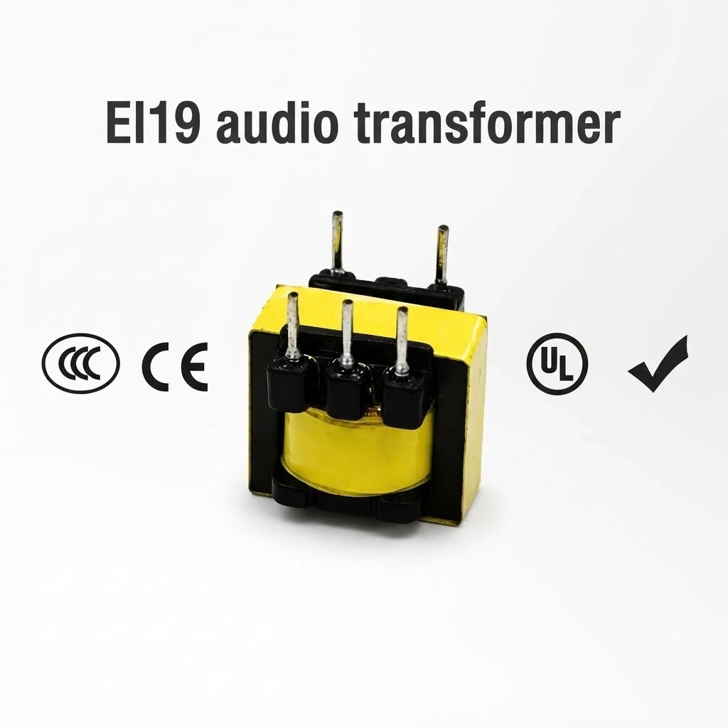
ZXY-EI19 in the EI19 hard-pin package, with the compliance marks carried on the product artwork
KEY HIGHLIGHTS
  • Four variants on one 19.5 x 15 x 17 mm body: 1:1, 1:5 and 1:11 turns ratio
  • Frequency range 100 Hz - 4.5 kHz, the band the series is specified over
  • Inductance 585 mH to 17 H at 1 kHz, 0.3 V signal, quoted as a minimum
  • DCR from 22 ohm to 1.58 kohm, held to plus or minus 15 percent
  • Hi-POT 500 V at 1 mA for 60 s on every model; DIP hard pins on 5 mm pitch
Pin numbers in the electrical table and on the schematic do not use the same pairs. The table specifies inductance and DC resistance for windings 1-2 and 3-4 and holds that convention for all four models. The published schematic draws the primary across terminals 3 and 1 and the secondary across 6 and 4, with the polarity dots at pins 1 and 4. Both refer to the same two windings, but the terminal numbers differ, so confirm the pin assignment of the exact model before laying out a footprint. Taken together the two documents name five terminals, 1, 2, 3, 4 and 6, which matches the five pins visible on the photographs, but neither document prints the full assignment on its own.
5.0
Model:
ZXY-EI19 (series
Frequency Range:
100 Hz - 4.5 kHz
Pin Pitch:
5 mm
Hi-POT:
500 V, 1 mA, 60 s
Package:
DIP plug-in through-hole, hard pin
Dimensions:
19.5 × 15 × 17 mm
DCR:
12.5 Ω - 1.58 kΩ, ±15 %
Inductance:
585 mH - 17 H at 1 kHz, 0.3 V, minimum per model
Turns Ratio:
1
Product Type:
EI19 hard-pin audio isolation and voice / data coupling transformer
design customization

    oops...!

    no product data.

    Go to homepage
    Test Temperature
    25 °C
    DCR Tolerance
    ±15 %
    DCR(3-4)
    28 Ω / 75 Ω / 12.5 Ω / 1.58 kΩ by model
    DCR(1-2)
    22 Ω / 60 Ω / 340 Ω / 71 Ω by model
    Inductance L(3-4)
    1.2 H / 585 mH / 150 mH / 17 H by model, 1 kHz 0.3 V min
    Inductance L(1-2)
    1.2 H / 585 mH / 2.9 H / 266 mH by model, 1 kHz 0.3 V min
    Winding Config
    Two separated windings, polarity dots at pins 1 and 4
    Hi-POT
    500 V, 1 mA, 60 s
    Package
    DIP plug-in through-hole, hard pin
    Model
    ZXY-EI19
    Frequency Range
    100 Hz - 4.5 kHz
    Product Type
    EI19 hard-pin audio isolation transformer
    Compliance
    CCC / CE / UL
    Mounting
    Through-hole, rigid pins, standard soldering
    Pin Pitch
    5 mm
    Body Depth
    15 mm
    Body Height
    17 mm
    Body Width
    19.5 mm
    Turns Ratio
    1
    Core
    EI19 laminated core, high-isolation core per artwork

    1. Product Name

    ZXY-EI19 EI19 hard-pin audio isolation and voice / data coupling transformer. DIP through-hole package, 19.5 x 15 x 17 mm, 5 mm pin pitch, turns ratio 1:1, 1:5 or 1:11 depending on model, frequency range 100 Hz to 4.5 kHz, Hi-POT 500 V at 1 mA for 60 s.

    Four views of the same part: nameplate face, both terminal rows and the laminated core edge
    Four views of the same part: nameplate face, both terminal rows and the laminated core edge
    Two parts side by side, hard pins facing the board
    Two parts side by side, hard pins facing the board

    Overview. The series is built around one body and one pin grid. What changes between the four models is the winding, not the package, so a board can be laid out once and populated with whichever ratio the circuit needs.

    Physically the part is a laminated EI19 core with a taped winding on a black bobbin, three terminals in a block on the front face and two more on the opposite edge. The core edges stay exposed, which is what makes the stack visible in the photographs and lets the winding be inspected after assembly.

    2. Feature

    Four variants on one footprint. EI1901 and EI1902 at 1:1, EI1904 at 1:5 and EI1905 at 1:11, all in the same 19.5 × 15 × 17 mm body with the same 5 mm pin pitch.

    100 Hz to 4.5 kHz. the working band for voice and data coupling, which is the range these parts are specified over rather than the full audio band.

    Inductance quoted as a minimum. 1.2 H on both windings of the EI1901, 585 mH on both of the EI1902, 2.9 H and 150 mH on the EI1904, 266 mH and 17 H on the EI1905, all at 1 kHz with a 0.3 V signal.

    DC resistance from 22 Ω. 22 Ω and 28 Ω on the EI1901, up to 1.58 kΩ on the second winding of the EI1905, every value held to ±15 %.

    Hi-POT 500 V on every model. 1 mA leakage limit held for 60 s, the same rating across the series.

    Hard pins, DIP through-hole. rigid terminals on a 5 mm pitch that hold the part in the board and take a standard solder joint without a carrier.

    High-isolation core. a laminated EI19 core with the windings separated on the bobbin and the polarity brought out to the published schematic.

    Yellow tape over the winding. the winding is taped and the core edges are left exposed, so the part can be inspected after winding.

    Customized designs available. factory-direct supply from stock, with custom windings on request.

    Series parameters: turns ratio 1:1, 1:5 or 1:11, inductance up to 1.2 H, DCR from 22 ohm, Hi-POT 500 V
    Series parameters: turns ratio 1:1, 1:5 or 1:11, inductance up to 1.2 H, DCR from 22 ohm, Hi-POT 500 V

    The series line on the artwork is worth reading closely: turns ratio 1:1, 1:5 and 1:11 with “various available”, inductance up to 1.2 H quoted against the EI1901, DC resistance as low as 22 Ω and Hi-POT 500 V. Those four numbers are the summary of the table in chapter 5.

    3. Advantage

    Protects the stage in front of it. the transformer isolates input from output, so a fault downstream cannot burn out the output of the equipment driving the line.

    Removes grounding hum. two separated windings break the signal-path ground connection, which is what takes out the AC hum that system grounding produces.

    Balanced and unbalanced lines. the same part reduces external interference in either arrangement.

    One footprint, four variants. a design that moves from 1:1 to 1:5 or 1:11 keeps its land pattern, its panel cutout and its assembly drawing.

    Rigid pins. through-hole terminals suit standard soldering and straightforward replacement, with no carrier or reflow profile to re-qualify.

    Precision pin spacing. the 5 mm grid is what lets the part drop into an existing DIP footprint without a custom land pattern.

    Two parts, winding visible through the yellow tape
    Two parts, winding visible through the yellow tape
    Two parts at different angles, showing the core stack and the terminal block
    Two parts at different angles, showing the core stack and the terminal block
    Three terminals on one row and two on the opposite edge, viewed with the pins up
    Three terminals on one row and two on the opposite edge, viewed with the pins up

    The pin grid is the practical advantage. A 5 mm pitch on a 19.5 mm body matches a standard DIP land pattern, so the part can replace a competitor device without a board revision, and the four ratios mean the same revision can serve a 1:1 isolation point and a 1:11 coupling point.

    4. Application

    The catalogue specification sheet lists four application areas for this part.

    Communication equipment. line and voice circuits where two pieces of equipment must not share a ground.

    Biomedical and medical devices. signal paths that need galvanic separation between the patient-side circuit and the rest of the instrument.

    Telephone and fax equipment. coupling a line interface to the set electronics, in the 100 Hz to 4.5 kHz band the part is specified over.

    Inductive (sensor) speakers. driving a high-impedance inductive load from a low-impedance amplifier output.

    Two EI19 transformers placed on a board, the second one turned to show its footprint
    Two EI19 transformers placed on a board, the second one turned to show its footprint
    Mounted on a green board next to the rest of the signal chain
    Mounted on a green board next to the rest of the signal chain

    In each of these the useful property is the same: two circuits that must exchange a signal but must not share a reference. A telephone line interface, a patient-side electrode circuit and a sensor speaker all sit on the far side of that boundary.

    5. Application Specifications

    Electrical data at 25 degrees C, as published for the series. Inductance is a minimum value measured at 1 kHz with a 0.3 V test signal; DC resistance carries a plus or minus 15 percent tolerance.

    5.1 Electrical specification by model

    ModelTurns ratioL(1-2)L(3-4)DCR(1-2)DCR(3-4)Hi-POT
    EI19011:11.2 H1.2 H22 Ω28 Ω500 V
    EI19021:1585 mH585 mH60 Ω75 Ω500 V
    EI19041:52.9 H150 mH340 Ω12.5 Ω500 V
    EI19051:11266 mH17 H71 Ω1.58 kΩ500 V
    Published pinout: winding terminals 3 and 1 on one side, 6 and 4 on the other, polarity dots at 1 and 4
    Published pinout: winding terminals 3 and 1 on one side, 6 and 4 on the other, polarity dots at 1 and 4

    5.2 Construction and mechanical data

    ItemValue
    CoreEI19 laminated core, described on the artwork as a high-isolation core
    PackageDIP plug-in, through-hole hard pin, with precision pin spacing
    Pin pitch5 mm, printed as 5*2 on the catalogue outline drawing
    Body dimensions19.5 mm wide × 15 mm deep × 17 mm high, excluding pin length
    Terminal rowsThree terminals on the front face, two on the opposite edge, as photographed
    WindingTwo separated windings with the polarity marked on the published schematic, dots at pins 1 and 4
    Body finishYellow tape over the winding, black terminal blocks, laminated core exposed at the edges

    5.3 Terminals on the published schematic

    TerminalFunction
    Terminal 3One end of the winding drawn on the left of the schematic
    Terminal 1Other end of the same winding; polarity dot
    Terminal 6One end of the winding drawn on the right
    Terminal 4Other end of that winding; polarity dot
    Pin numbers in the electrical table and on the schematic do not use the same pairs. The table specifies inductance and DC resistance for windings 1-2 and 3-4 and holds that convention for all four models. The published schematic draws the primary across terminals 3 and 1 and the secondary across 6 and 4, with the polarity dots at pins 1 and 4. Both refer to the same two windings, but the terminal numbers differ, so confirm the pin assignment of the exact model before laying out a footprint. Taken together the two documents name five terminals, 1, 2, 3, 4 and 6, which matches the five pins visible on the photographs, but neither document prints the full assignment on its own.
    Two dimension graphics supplied with this model are internally inconsistent and are not reproduced on this page. One carries the header EE-type high-frequency transformer, which does not describe an EI19 audio part rated from 100 Hz to 4.5 kHz; the other prints 19 mm for a body dimension that the same drawing set gives as 19.5 mm and leaves one callout without a value. The dimensions quoted here are the ones stated in the specification document and the catalogue outline drawing: 19.5 x 15 x 17 mm, pin pitch 5 mm.

    6. Quality & Testing Assurance

    Each parameter below is published with its test condition. Every model in the series carries the same dielectric withstand rating, and the part is marked CCC, CE and UL.

    ParameterTest condition and specification
    Inductance (L)1 kHz, 0.3 V test signal, quoted as a minimum value per model
    DC resistance (DCR)Tolerance ±15 %
    Dielectric withstand (Hi-POT)500 V, leakage limit 1 mA, held 60 s, all four models
    Turns ratio1:1 (EI1901, EI1902); 1:5 (EI1904); 1:11 (EI1905)
    Reference temperature25 °C for all electrical parameters
    Frequency range100 Hz to 4.5 kHz
    The compliance marks appear on the product artwork supplied with this listing. No certificate numbers or issuing bodies were supplied, so confirm the certificate numbers and the scope of each mark before publishing a certification claim.

    Brand / manufacturer: ZXY, Shenzhen Zhixiangyuan Electronics Co., Ltd. http://www.zxycoil.com

    Message Form
    We Can Help You Solve Any Problem 
    Just leave your email or phone number in the contact form so we can send you a free quote for our wide range of designs!
    Related Products
    Huizhou Company Address
    Zhixiangyuan Technology Co., Ltd., 5th Floor, Building 4, Xinghe Industrial Park, Zhongkai High tech Zone, Huicheng District, Huizhou City, Guangdong Province
    Contact Us
    Contact Person: Rhea Chen
    Tel/WhatsApp: +86 13554723725
    Fax: 86-0755-23779620
    Shenzhen Company Address
    Room 202, Yingfei Haocheng Science and Technology Park, Guansheng 5th Road, Luhu Community, Guanhu Street, Longhua District, Shenzhen City, Guangdong Province, China
    Customer service
    detect