


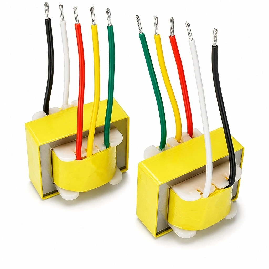
ZXY-EE25 Flying-Lead Audio Isolation Transformer - 1:4 Turns Ratio | 65mH / 900mH Inductance | AC 500V Isolation | CCC CE RoHS UL
The ZXY-EE25 is a compact audio isolation transformer built on a high-grade EE25 silicon-steel core and terminated with multi-color flying leads. With a 1:4 turns ratio, an inductance range of 65 mH to 900 mH at 1 kHz and pre-stripped, tinned copper lead tips, it provides impedance matching, galvanic signal isolation and ground-loop noise rejection in professional audio, broadcast, communication and industrial audio equipment.
- 1 : 4 turns ratio, 65 mH / 900 mH inductance at 1 kHz
- AC 500 V dielectric isolation, insulation resistance ≥ 100 MΩ
- Low DCR 1.55 Ω / 17.5 Ω for low insertion loss
- Multi-color flying leads, pre-stripped and tinned copper tips
- UL94V-0 flame-retardant bobbin, CCC / CE / RoHS / UL, ISO 9001:2015
1. Product Overview
The ZXY-EE25 is a compact audio isolation transformer built on a high-grade EE25 silicon-steel core and terminated with multi-color flying leads. With a 1:4 turns ratio, an inductance range of 65 mH to 900 mH at 1 kHz and pre-stripped, tinned copper lead tips, it provides impedance matching, galvanic signal isolation and ground-loop noise rejection in professional audio, broadcast, communication and industrial audio equipment.
Figure 1 — EE25 flying-lead audio isolation transformer, multi-color leads, tinned copper tips.
At a glance
| Parameter | Value |
|---|---|
| Turns ratio | 1 : 4 |
| Inductance (red–blue) | 900 mH typ. (800 mH min) @ 1 kHz |
| Inductance (yellow–green) | 65 mH typ. (56 mH min) @ 1 kHz |
| DC resistance (DCR) | 1.55 Ω / 17.5 Ω (±10%) |
| Hi-Pot dielectric withstand | AC 500 V / 2 mA / 3 s, no breakdown |
| Insulation resistance | ≥ 100 MΩ @ 500 V DC |
| Dimensions (L × W × H) | 26.0 × 19.0 × 14.8 mm |
2. Key Features
- High-grade EE25 core frame — Premium silicon-steel core for low loss, high efficiency and stable performance.
- Multi-color flying lead wires — Black, white, red, yellow and green leads are color-coded for easy identification and secure connections.
- Pre-stripped and tinned copper tips — Ready for soldering, ensuring fast and reliable installation.
- Flame-retardant nylon bobbin — High-temperature resistant UL94V-0 material for enhanced safety and durability.
- High-purity enameled copper wire — Consistent, low-distortion signal transfer from a 0.025–2.0 mm winding wire.
- Class B/F high dielectric insulation — Reliable dielectric isolation of AC 500 V between windings.
- 26.0 × 19.0 × 14.8 mm envelope — A compact body that fits dense PCB and chassis layouts.
Figure 2 — Key construction features of the EE25 flying-lead transformer.
Figure 3 — Winding wire, dielectric insulation, magnetic core and bobbin material.
3. Advantages
- Accurate 1:4 turns ratio — Stable inductance of 65 mH / 900 mH at 1 kHz delivers repeatable impedance matching.
- Low winding resistance — DCR of only 1.55 Ω / 17.5 Ω keeps insertion loss low and preserves signal level.
- Faithful audio transfer — Flat audio response and low harmonic distortion across the low-frequency and audio range make the EE25 suitable for high-fidelity signal paths.
- Dielectric isolation — AC 500 V, 50 Hz withstand breaks ground loops and blocks common-mode noise between equipment stages.
- Stable insulation — Insulation resistance of ≥ 100 MΩ at 500 V DC supports long-term reliability.
- Certified quality — UL-approved leads, CCC / CE / RoHS / UL compliance and ISO 9001:2015 production.
Figure 4 — Audio-grade electrical performance and dielectric withstand.
4. Applications
Core functions: Impedance matching · signal isolation · noise reduction (ground loop) · balanced-to-unbalanced conversion
- Professional audio and video equipment — Tube (valve) amplifiers, DI boxes, microphones, mixing consoles and high-end sound cards.
- Broadcast and public address systems — Audio signal converters, telephone couplers and industrial audio isolators.
- Communication and voice equipment — Intercoms, fax machines, vehicle radios, VoIP devices and recording equipment.
- Home audio products — Radios, hi-fi systems, home-theatre equipment and passive speaker accessories.
- Industrial, security and medical — Audio separators, noise suppressors, access-control voice units, surveillance pickups and monitor voice channels.
Figure 5 — EE25 transformer installed in a professional microphone preamplifier front-end.
5. Specifications
5.1 Electrical Parameters (≈ 25 °C)
| Parameter | Test condition | Value |
|---|---|---|
| Turns ratio | — | 1 : 4 |
| Inductance (red–blue winding) | 1 kHz, 0.3 V | 900 mH typ. (800 mH min) |
| Inductance (yellow–green winding) | 1 kHz, 0.3 V | 65 mH typ. (56 mH min) |
| DC resistance (DCR) | 25 °C | 1.55 Ω / 17.5 Ω (±10%) |
| Hi-Pot dielectric withstand | AC 500 V, 2 mA, 3 s | No breakdown |
| Insulation resistance | 500 V DC | ≥ 100 MΩ |
| Dielectric insulation class | — | Class B / F |
Measured at 1 kHz / 0.3 V for inductance; DCR tolerance ±10%, in accordance with the product specification sheet.
Figure 6 — Rated inductance, DCR, Hi-Pot isolation and insulation resistance.
5.2 Mechanical Data
| Item | Specification |
|---|---|
| Core | EE25 frame, high-grade silicon steel |
| Overall dimensions (L × W × H) | 26.0 × 19.0 × 14.8 mm |
| Termination | Multi-color flying leads (black, white, red, yellow, green) |
| Lead preparation | Pre-stripped, tinned copper tips |
| Winding wire | High-purity enameled copper wire, 0.025–2.0 mm |
| Bobbin material | Flame-retardant nylon, UL94V-0 |
All dimensions and performance parameters can be developed and customized to customer requirements.
Figure 7 — Multi-angle overview, compact EE25 size and lead outlines.
Figure 8 — Winding and bobbin close-up.
Figure 9 — Pre-stripped, tinned copper lead tips.
6. Quality & Testing Assurance
- Controlled manufacturing — Every transformer is produced under an ISO 9001:2015 quality management system.
- Hi-Pot test — AC 500 V, 2 mA for 3 s, non-breakdown.
- Insulation resistance — ≥ 100 MΩ at 500 V DC.
- Flame retardancy — UL94V-0 flame-retardant bobbin and UL-approved leads.
- Compliance — CCC, CE, RoHS and UL.
Figure 10 — International certification and quality compliance.
Figure 11 — Routine dielectric and insulation-resistance verification of EE25 units.
Safe · Reliable · Compliant