
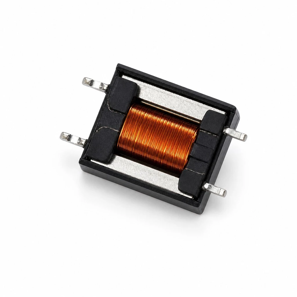
ZXY-B2511 Permalloy Audio Isolation Transformer, 1:1, 1.0 H, 300 Hz to 4 kHz, Compact SMD
ZXY-B2511 is a cased permalloy audio isolation transformer with two separate 1:1 windings, built for low-frequency signal paths. Both windings measure 110 Ω ±10 % DC resistance and 1.0 H minimum inductance at 1 kHz / 0.3 V, and the turns ratio is held to 1:1 ±2 %. Frequency response stays within ±0.12 dB from 300 Hz to 4 kHz referred to 1 kHz. Insulation resistance is 100 MΩ min at 200 VDC with a 1,250 VDC hi-pot at 1 mA for 60 s between windings. Body 12.0 mm by 9.3 mm, 5.8 mm high, on four SMD gull-wing pins.
- Two separate 1:1 windings, each 110 Ω ±10 % DCR and 1.0 H min at 1 kHz / 0.3 V
- Turns ratio 1:1 ±2 %, measured at 15 kHz and 1 V
- Permalloy ED8×10 core from Jiangsu Hongyun Precision Industry, cased construction
- Frequency response within ±0.12 dB from 300 Hz to 4 kHz, referred to 1 kHz
- Insulation resistance 100 MΩ min at 200 VDC; hi-pot 1,250 VDC at 1 mA for 60 s
- Body 12.0 mm by 9.3 mm, 5.8 mm high, four SMD gull-wing pins on a 14.0 mm span
1. Product Name
ZXY-B2511, a cased permalloy audio isolation transformer with two separate 1:1 windings: an ED8×10 permalloy core from Jiangsu Hongyun Precision Industry, wound on a Sumitomo Bakelite PM9820 bobbin with 2UEW-H 180 °C wire, taped with PF (8) tape, varnished with E962 and terminated in lead-free Sn-0.3Ag-0.7Cu solder. Four SMD gull-wing pins; body 12.0 mm max by 9.3 mm max and 5.8 mm max high. Specification first issued 2025-02-18 as part B2511, ED8×10-1.0H cased.
A closed part. The winding sits inside a black housing that shuts over it, and the only metal left exposed is the four gull-wing terminals that project past the case edge. Nothing about the coil is loose on the outside, so the part can be placed, reflowed and cleaned like any other SMD block.
2. Construction & Materials
The core. Permalloy, an ED8×10 stack supplied by Jiangsu Hongyun Precision Industry. Permalloy is a high-permeability nickel-iron, and its advantage is at the bottom of the band: at 300 Hz it reaches an inductance that a ferrite core of the same volume cannot, which is what the 1.0 H floor at 1 kHz is built on. The case closes over the core, so the magnetic circuit is also shielded from stray fields around it.
The winding and the wire. Two separate windings of equal turns, wound with 2UEW-H enamel wire rated to 180 °C and covered by UL file E193774. The high temperature rating is what allows the part to pass through a reflow oven and still hold its DCR window: 110 Ω ±10 % on pins 1-2 and the same on pins 3-4.
The insulation system. The bobbin is Sumitomo Bakelite PM9820 under UL file E41429, taped with PF (8) tape under UL file E165111 and varnished with E962 under UL file E335405. Each material is named by supplier and file number so the bill of materials can be audited line by line, which is the part of the specification a safety reviewer reads first.
The casing is a shield as well as a box. It closes the magnetic circuit's exposure to nearby fields and it protects a coil wound with fine enamel wire from handling damage between the winding line and the reflow oven.
3. Feature
1:1 on two separate windings. Two independent windings of equal turns, each measuring 110 Ω ±10 % DC resistance and 1.0 H minimum inductance at 1 kHz / 0.3 V. Equal windings on a common core are what let either side drive or be driven, and what holds the ratio to ±2 %.
Permalloy core, ED8×10. The core is permalloy, a high-permeability nickel-iron, supplied as an ED8×10 stack by Jiangsu Hongyun Precision Industry. At 300 Hz a permalloy core reaches the inductance a ferrite of the same volume cannot, which is what the 1.0 H floor at 1 kHz is built on.
Cased construction. The winding sits in a black housing that closes over it, with the four terminals formed into gull wings that project past the case. The casing shields the coil from nearby fields and protects it in handling.
Flat response over the speech and programme band. Frequency response is held within ±0.12 dB from 300 Hz to 4 kHz referred to 1 kHz, which is tight enough that the transformer does not colour the signal it passes.
Separate windings, stated as figures. Insulation resistance of 100 MΩ min at 200 VDC and a 1,250 VDC hi-pot at 1 mA for 60 s between the windings, both acceptance items on every unit rather than a type-test claim.
Traceable materials. Bobbin, wire, tape and varnish are each named by supplier and UL file number, and the termination is lead-free Sn-0.3Ag-0.7Cu solder, so the bill of materials can be audited line by line.
4. Advantage
High permeability at low frequency. Permalloy holds its permeability far lower in the band than ferrite, so the part reaches 1.0 H at 1 kHz in a body of 12.0 by 9.3 by 5.8 mm. That is the reason to specify this core rather than a ferrite one.
Symmetrical by measurement, not by claim. Both windings are quoted at the same 110 Ω ±10 % DCR and the same 1.0 H floor, so the two sides are interchangeable in a circuit and the ratio does not drift with which way round the part is fitted.
±0.12 dB across 300 Hz to 4 kHz. Response that flat over the band means the transformer is a pass-through element: what goes in comes out at the same level, and the design margin is spent elsewhere.
A footprint the layout can plan around. Body 12.0 by 9.3 mm, pins on a 14.0 mm span with a 5.08 mm row grid and 0.7 by 1.05 mm pads, all given as numbers, so the land pattern drops into a library instead of being traced from a sample.
Isolation stated as a test. 1,250 VDC at 1 mA for 60 s between windings, plus 100 MΩ at 200 VDC, both specified as acceptance items. Where a design has to demonstrate separation, these are the figures a test house will ask for.
Materials you can trace. Four UL file numbers cover the bobbin, the wire, the tape and the varnish, and the wire is rated to 180 °C, so the part suits equipment that has to show its material declarations.
5. Application
Low-frequency line and signal isolation. 1:1 coupling across a barrier from 300 Hz to 4 kHz, which covers speech, programme material and the signalling band above it.
Between audio stages or between pieces of equipment. Where two sides sit at different ground potentials, the transformer carries the signal and leaves the grounds apart, which is what breaks a loop that would otherwise appear as hum.
Compact SMD audio boards. A 12.0 by 9.3 mm cased body on four gull-wing pins places and reflows with the rest of the board, so a low-frequency permalloy transformer does not have to be a hand-fitted wired part.
Custom permalloy builds. Where the standard 1:1 build does not fit, the same core and case are wound to a customer drawing or sample, with the acceptance table issued against that drawing.
On a board the part sits between the audio output and whatever comes next, and its job is to carry the signal across a barrier without joining the two grounds. Level and response should not change; if they do, the part is being used as a matching device and the figures here no longer describe what the circuit sees.
6. Specifications
The data below is the approved specification for ZXY-B2511, reproduced as declared.
6.1 Summary
| Parameter | Specification | Test condition / note |
|---|---|---|
| Model | ZXY-B2511 | ED8×10-1.0H cased build |
| Type | 1:1 audio isolation transformer | Cased SMD construction |
| Windings | Two separate 1:1 windings | Pins 1-2 and pins 3-4 |
| Turns ratio | 1:1 ±2 % | 15 kHz, 1 V |
| DC resistance | 110 Ω ±10 % | Pins 1-2 and pins 3-4 |
| Inductance | 1.0 H min | 1 kHz, 0.3 V |
| Frequency response | ±0.12 dB | 300 Hz to 4 kHz, ref 1 kHz |
| Insulation resistance | ≥100 MΩ | At 200 VDC |
| Hi-pot | 1,250 VDC, 1 mA, 60 s | Between windings |
| Core | Permalloy, ED8×10 | Jiangsu Hongyun Precision Industry |
| Body | 12.0 mm max × 9.3 mm max, 5.8 mm max high | Per engineering drawing |
| Compliance | RoHS compliant | — |
6.2 Electrical
| Parameter | Specification | Test condition |
|---|---|---|
| DC resistance | 110 Ω ±10 % | Pins 1-2 and pins 3-4 |
| Inductance | 1.0 H min | 1 kHz, 0.3 V, on pins 1-2 and 3-4 |
| Turns ratio | 1:1 ±2 % | 15 kHz, 1 V |
| Frequency response | ±0.12 dB | 300 Hz to 4 kHz, referred to 1 kHz |
| Insulation resistance | ≥100 MΩ | At 200 VDC |
| Hi-pot | 1,250 VDC, 1 mA, 60 s | Between windings, SEC : P-S as written |
| RoHS | Compliant | — |
6.3 Mechanical and footprint
| Dimension | Value | Note |
|---|---|---|
| Body length | 12.0 mm max | Per engineering drawing |
| Body width | 9.3 mm max | Per engineering drawing |
| Height | 5.8 mm max | Above the seating plane |
| Pin span | 14.0 ±0.5 mm | Outer pin to outer pin, overall |
| Pin spacing | 5.0 ±0.3 mm | Between the two pins of one edge |
| Terminals | 4 SMD gull-wing pins | Two on each long edge |
| Pad size | 0.7 × 1.05 mm | PCB land |
| Row spacing | 5.08 mm | PCB land |
| Pad span | 14.6 mm | PCB land, outer pad to outer pad |
6.4 Construction
| Item | Specification | Note |
|---|---|---|
| Core | Permalloy, ED8×10 | Jiangsu Hongyun Precision Industry |
| Bobbin | Sumitomo Bakelite PM9820 | UL file E41429 |
| Winding wire | 2UEW-H, 180 °C rated | UL file E193774 |
| Tape | PF (8) tape | UL file E165111 |
| Varnish | E962 | UL file E335405 |
| Termination | Lead-free Sn-0.3Ag-0.7Cu solder | RoHS compatible |
| Housing | Cased, closed over the winding | Shielded casing |
6.5 Quality and testing
| Item | Requirement | Condition |
|---|---|---|
| Acceptance items | DCR, inductance, turns ratio, frequency response, insulation resistance, hi-pot | Defined for every unit |
| Dielectric strength | 1,250 VDC at 1 mA for 60 s | Between windings |
| Insulation resistance | 100 MΩ min at 200 VDC | Between windings |
| Material traceability | Core supplier, bobbin, wire, tape and varnish each named with a UL file number | Per specification |
| Document control | Specification for approval first issued 2025-02-18 | Part B2511, ED8×10-1.0H cased |
7. Ordering
The part is ordered as ZXY-B2511. The core, bobbin, case and pin-out are the fixed part of the design; the winding and the turns ratio can be built to a customer drawing or sample where the standard 1:1 build does not fit the equipment. Where a build differs, state the ratio and the impedance with the order so the acceptance table can be issued against it.
Brand / manufacturer: ZXY, Shenzhen Zhixiangyuan Electronics Co., Ltd. http://www.zxycoil.com