
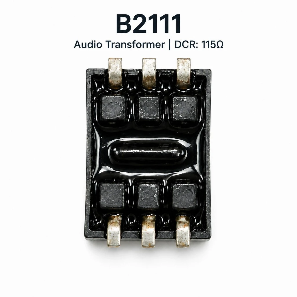
ZXY-B2111 Audio Isolation Transformer, 1:1 600 Ohm Line Audio Transformer, SMD Potted, 4.6 kV Hi-Pot
ZXY-B2111 is a 1:1 audio isolation transformer for 600 Ω line systems, built on an ED8×11 nickel-steel lamination core and supplied as a fully potted SMD body. Both windings are 520 turns of 2UEW-F Ø0.04 mm enamel wire on a thickened double-section bobbin. Turns ratio 1 ±1 %, DC resistance 115 Ω ±10 % on each winding, inductance 1.4 H min, insertion loss 2 dB max at 2 kHz and return loss 24 dB min from 200 Hz to 4 kHz in a 600 Ω system. Body 13.8 mm by 10.6 mm, 8.0 mm high.
- 1:1 turns ratio within ±1 %, measured at 15 kHz and 1 V on pins 1-3 and 4-6
- ED8×11 nickel-steel lamination core, 0.15 mm grade PC, interleaved and fully stacked
- 2UEW-F Ø0.04 mm enamel wire, 520 turns per winding, double-section thickened bobbin
- Insertion loss 2 dB max at 2 kHz; return loss 24 dB min in a 600 Ω system
- Frequency response within ±0.25 dB from 200 Hz to 4 kHz
- Hi-pot 4,600 VDC at 1 mA for 60 s; insulation resistance 100 MΩ min at 200 VDC
1. Product Name
ZXY-B2111, 1:1 600 Ω audio isolation transformer: an ED8×11 nickel-steel lamination core with 0.15 mm grade PC laminations interleaved and fully stacked, 520 turns of 2UEW-F Ø0.04 mm enamel wire on each of two windings, a thickened double-section bobbin, and a black high-temperature housing fully potted over the assembly. Six SMD gull-wing pins in two rows of three. Body 13.8 mm max by 10.6 mm max and 8.0 mm max high.
Two faces, one part. One face carries the six terminals and the potted winding; the other is a plain moulded wall. Because the fill is inside the case, the outside of the part is a closed block, and nothing about the winding is exposed to handling, cleaning or reflow.
2. Construction & Materials
The core. ED8×11 nickel-steel laminations, 0.15 mm thick and of grade PC, interleaved and fully stacked. Nickel-steel is chosen because at the bottom of the audio band a laminated nickel-iron core saturates later than a ferrite of the same volume, which is what lets the part hold 1.4 H and stay inside ±0.25 dB down at 200 Hz. The thin foil keeps eddy currents small at these frequencies, and interleaving joins the two halves of the magnetic circuit with many overlapping seams rather than one butt joint.
The two details that decide the ratings. The isolation barrier is the wall between the two winding sections, and it is why the hi-pot is 4,600 VDC: the bobbin is thickened and split into two sections, so the windings are separated by moulded material plus the fill rather than by tape alone. The lead is a formed gull-wing, which is what makes the part a reflow component; the recommended profile peaks at 260 °C and the housing is heat tested to 280 °C.
The seal. The epoxy resin sits over the winding face and stops short of the solderable part of the pins. That boundary is deliberate: the fill has to cover the coil to seal it and hold the core tight, and it must not creep onto the terminals, because a pin with resin on it will not wet properly in the oven.
Both windings are 520 turns of 2UEW-F Ø0.04 mm enamel wire. Equal turns on equal windings is what makes the two sides interchangeable and what holds the ratio to ±1 %. The specification adds a workmanship requirement that the windings are laid flat, because a winding that crosses back over itself adds wire length and pushes the DC resistance out of the ±10 % window.
3. Feature
Matched 1:1 windings. Both windings are 520 turns of the same wire on the same bobbin, and the ratio is held to ±1 % when measured at 15 kHz and 1 V across pins 1-3 and 4-6. Equal turns on equal windings is what makes the part usable as a balanced line isolator rather than only as a step device.
ED8×11 nickel-steel lamination core. The core is built from 0.15 mm nickel-steel laminations of grade PC, interleaved and fully stacked. Interleaving puts alternate laminations in opposite orientation, so the joint between the two halves of the stack never lines up in one plane, and full stacking leaves no gap in the magnetic path.
Thickened double-section bobbin. The bobbin is split into two sections and thickened, which separates the two windings physically and provides the wall thickness the 4,600 VDC hi-pot rating depends on.
Fully potted housing. The body is a black high-temperature-resistant shell filled over the core and the winding. The fill holds the assembly rigid, keeps moisture out of the winding, and lets the part be handled and reflowed without the core moving inside the case.
Six SMD gull-wing terminals. Three pins per row, formed into gull wings, so the part is placed and reflowed with the rest of the board. The recommended profile peaks at 260 °C and the housing is heat endurance tested to 280 °C.
4. Advantage
Flat response across the specified band. Response is held inside ±0.25 dB from 200 Hz to 4 kHz referred to 2 kHz. In a 600 Ω line that is what stops the part colouring the signal it passes, which is the whole point of fitting an isolation transformer in the first place.
Return loss in a 600 Ω system. 24 dB minimum across the same band means the part presents something close to 600 Ω at both ends, so it reflects little energy back down the line and does not produce the ripple a mismatch causes.
Low insertion loss. 2 dB maximum at 2 kHz with the secondary terminated in 412 Ω. A transformer that loses less level needs less make-up gain downstream, and less gain means less noise added to the signal.
Dielectric strength stated as a test. 4,600 VDC at a 1 mA leakage limit for 60 s between secondary and primary, with insulation resistance of 100 MΩ minimum at 200 VDC. Both are acceptance items on every unit rather than a type-test claim.
Small potted body for a dense board. 13.8 mm by 10.6 mm and 8.0 mm high, with the six pins on a 5 mm same-row span and the rows 11.0 mm apart, so the footprint is a rectangle the layout can plan around instead of a wire-ended part that has to be hand placed.
5. Application
Line isolation between audio stages. Where two stages sit at different ground potentials inside one chassis, a 1:1 transformer carries the signal across without joining the two grounds together.
Isolation between pieces of equipment. Between two units on a 600 Ω-referenced line the part breaks the earth loop that would otherwise appear as hum, and holds the level on both sides of the break.
Signal transmission from 200 Hz to 4 kHz. The specified band covers speech and programme material, and the ±0.25 dB window is quoted over that band rather than over the whole audio range.
Positions needing verified galvanic isolation. Where the design has to demonstrate separation between the windings, the 4,600 VDC hi-pot and the 100 MΩ insulation resistance are the two figures a test house will ask for.
In a signal chain the part sits between a source and the next stage and carries the signal across a barrier without joining the two grounds. Level and response should not change.
6. Specifications
The data below is the approved specification for ZXY-B2111, reproduced as declared.
6.1 Summary
| Parameter | Specification | Test condition / note |
|---|---|---|
| Model | ZXY-B2111 | — |
| Type | 1:1 audio isolation transformer | Potted SMD construction |
| Turns ratio | 1 ±1 % | 15 kHz, 1 V, pins 1-3 : 4-6 |
| System impedance | 600 Ω | Referenced for insertion and return loss |
| Core | ED8×11 nickel-steel lamination, 0.15 mm, grade PC | Interleaved, fully stacked |
| Bobbin | ED8×11, double-section, thickened | — |
| Winding | 2UEW-F Ø0.04 mm enamel wire, 520 turns per winding | Both windings |
| Housing | Black high-temperature-resistant material | Fully potted |
| Terminals | 6 SMD gull-wing pins, 3 per row | Reflow compatible |
| Body | 13.8 mm max × 10.6 mm max, 8.0 mm max high | Per engineering drawing |
| Dielectric | 4,600 VDC, 1 mA, 60 s | Acceptance item on every unit |
| Compliance | RoHS compliant | — |
6.2 Electrical
| Parameter | Specification | Test condition |
|---|---|---|
| DC resistance | 115 Ω ±10 % | Pins 1-3 |
| DC resistance | 115 Ω ±10 % | Pins 4-6 |
| Inductance | 1.4 H min | Ls, 1 kHz, 0.25 V |
| Parallel resistance | 7,500 Ω min | — |
| Insertion loss | 2 dB max | 2 kHz, 0 dB ref, pins 1-3, pins 4-6 with 412 Ω |
| Return loss | 24 dB min | Ref 600 Ω, from 200 Hz to 4 kHz |
| Turns ratio | 1 ±1 % | 15 kHz, 1 V, pins 1-3 : 4-6 |
| Frequency response | ±0.25 dB | Ref 2 kHz, from 200 Hz to 4 kHz |
| Insulation resistance | 100 MΩ min | At 200 VDC |
| Hi-pot | 4,600 VDC, 1 mA, 60 s | Secondary to primary |
| RoHS | Compliant | — |
6.3 Mechanical and footprint
| Dimension | Value | Note |
|---|---|---|
| Body footprint | 13.8 mm max × 10.6 mm max | Per engineering drawing |
| Height | 8.0 mm max | Per engineering drawing |
| Span across pins | 14 ±0.5 mm | Per engineering drawing |
| Pin spacing, same row | 5 ±0.3 mm between outer pins | 3 pins per row, 6 pins total |
| Pin rows | 11.0 ±0.1 mm | Axis to be confirmed, see Appendix B |
| Mounting | SMD gull-wing pins, reflow compatible | Peak 260 °C in the recommended profile |
| Heat endurance | Peak 280 °C | Test data in the specification, page 4 |
| Winding finish | Windings laid flat | To avoid excessive DC resistance |
6.4 Construction
| Item | Specification | Note |
|---|---|---|
| Core | ED8×11 nickel-steel lamination, 0.15 mm, grade PC | Interleaved and fully stacked |
| Bobbin | ED8×11, double-section, thickened | Two winding sections |
| Winding | 2UEW-F Ø0.04 mm enamel wire, 520 turns per winding | Both windings |
| Housing | Black high-temperature-resistant material | Fully potted |
| Sealing | Epoxy resin over the potted face | As shown on the detail view |
| Terminals | 6 SMD gull-wing pins | 3 per row |
6.5 Quality and testing
| Item | Requirement | Condition |
|---|---|---|
| Acceptance items | DCR on both windings, inductance, parallel resistance, insertion loss, return loss, turns ratio, frequency response, insulation resistance, hi-pot | Defined for every unit |
| Dielectric strength | 4,600 VDC at 1 mA for 60 s | Specified, not sampled |
| Insulation resistance | 100 MΩ min at 200 VDC | Specified, not sampled |
| Workmanship | Windings laid flat to prevent excessive DC resistance | Per specification |
| Core stacking | 0.15 mm nickel-steel laminations, interleaved and fully stacked | Per specification |
| Materials | 2UEW-F enamel wire, black high-temperature potted housing | RoHS compliant |
7. Ordering
The part is ordered as ZXY-B2111. The core, bobbin and housing are the fixed part of the design; the winding, the turns ratio and the pin-out can be built to a customer drawing where the standard 600 Ω 1:1 build does not fit the equipment. Where a build differs, state the ratio and the impedance with the order so the acceptance table can be issued with it.
Brand / manufacturer: ZXY, Shenzhen Zhixiangyuan Electronics Co., Ltd. http://www.zxycoil.com