loading

ZXY: 26 Years of Excellence as a Leading Transformer and Inductor Manufacturer ・ One-Stop Solutions

EL14 Horizontal Audio Isolation Transformer, Through-Hole PCB Mount, 300 Hz - 3.4 kHz, 1:1 Turns Ratio, EI1401 / EI1402, 16 x 8.5 mm 1
EL14 Horizontal Audio Isolation Transformer, Through-Hole PCB Mount, 300 Hz - 3.4 kHz, 1:1 Turns Ratio, EI1401 / EI1402, 16 x 8.5 mm 2
EL14 Horizontal Audio Isolation Transformer, Through-Hole PCB Mount, 300 Hz - 3.4 kHz, 1:1 Turns Ratio, EI1401 / EI1402, 16 x 8.5 mm 3
EL14 Horizontal Audio Isolation Transformer, Through-Hole PCB Mount, 300 Hz - 3.4 kHz, 1:1 Turns Ratio, EI1401 / EI1402, 16 x 8.5 mm 4
EL14 Horizontal Audio Isolation Transformer, Through-Hole PCB Mount, 300 Hz - 3.4 kHz, 1:1 Turns Ratio, EI1401 / EI1402, 16 x 8.5 mm 5
EL14 Horizontal Audio Isolation Transformer, Through-Hole PCB Mount, 300 Hz - 3.4 kHz, 1:1 Turns Ratio, EI1401 / EI1402, 16 x 8.5 mm 6
EL14 Horizontal Audio Isolation Transformer, Through-Hole PCB Mount, 300 Hz - 3.4 kHz, 1:1 Turns Ratio, EI1401 / EI1402, 16 x 8.5 mm 7
EL14 Horizontal Audio Isolation Transformer, Through-Hole PCB Mount, 300 Hz - 3.4 kHz, 1:1 Turns Ratio, EI1401 / EI1402, 16 x 8.5 mm 8
EL14 Horizontal Audio Isolation Transformer, Through-Hole PCB Mount, 300 Hz - 3.4 kHz, 1:1 Turns Ratio, EI1401 / EI1402, 16 x 8.5 mm 9
EL14 Horizontal Audio Isolation Transformer, Through-Hole PCB Mount, 300 Hz - 3.4 kHz, 1:1 Turns Ratio, EI1401 / EI1402, 16 x 8.5 mm 10
EL14 Horizontal Audio Isolation Transformer, Through-Hole PCB Mount, 300 Hz - 3.4 kHz, 1:1 Turns Ratio, EI1401 / EI1402, 16 x 8.5 mm 1
EL14 Horizontal Audio Isolation Transformer, Through-Hole PCB Mount, 300 Hz - 3.4 kHz, 1:1 Turns Ratio, EI1401 / EI1402, 16 x 8.5 mm 2
EL14 Horizontal Audio Isolation Transformer, Through-Hole PCB Mount, 300 Hz - 3.4 kHz, 1:1 Turns Ratio, EI1401 / EI1402, 16 x 8.5 mm 3
EL14 Horizontal Audio Isolation Transformer, Through-Hole PCB Mount, 300 Hz - 3.4 kHz, 1:1 Turns Ratio, EI1401 / EI1402, 16 x 8.5 mm 4
EL14 Horizontal Audio Isolation Transformer, Through-Hole PCB Mount, 300 Hz - 3.4 kHz, 1:1 Turns Ratio, EI1401 / EI1402, 16 x 8.5 mm 5
EL14 Horizontal Audio Isolation Transformer, Through-Hole PCB Mount, 300 Hz - 3.4 kHz, 1:1 Turns Ratio, EI1401 / EI1402, 16 x 8.5 mm 6
EL14 Horizontal Audio Isolation Transformer, Through-Hole PCB Mount, 300 Hz - 3.4 kHz, 1:1 Turns Ratio, EI1401 / EI1402, 16 x 8.5 mm 7
EL14 Horizontal Audio Isolation Transformer, Through-Hole PCB Mount, 300 Hz - 3.4 kHz, 1:1 Turns Ratio, EI1401 / EI1402, 16 x 8.5 mm 8
EL14 Horizontal Audio Isolation Transformer, Through-Hole PCB Mount, 300 Hz - 3.4 kHz, 1:1 Turns Ratio, EI1401 / EI1402, 16 x 8.5 mm 9
EL14 Horizontal Audio Isolation Transformer, Through-Hole PCB Mount, 300 Hz - 3.4 kHz, 1:1 Turns Ratio, EI1401 / EI1402, 16 x 8.5 mm 10

EL14 Horizontal Audio Isolation Transformer, Through-Hole PCB Mount, 300 Hz - 3.4 kHz, 1:1 Turns Ratio, EI1401 / EI1402, 16 x 8.5 mm

EL14 horizontal audio transformer | through-hole | 300 Hz - 3.4 kHz | 1:1 | ferrite core

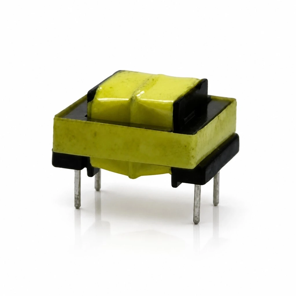
EL14 is a horizontal audio isolation transformer for through-hole PCB mounting: a precision ferrite core, a precision coil with the primary on pins 1-2 and the secondary on pins 4-3 under yellow tape insulation, and four pins in two rows. Two variants, EI1401 and EI1402, both 1:1 and both rated 1500 V at 1 mA / 60 s. 300 Hz to 3.4 kHz. Body 16 mm maximum length, 8.5 mm high.

EL14 horizontal audio transformer: ferrite core under a yellow tape wrap, four through-hole pins below the body
KEY HIGHLIGHTS
  • Turns ratio 1:1, primary on pins 1-2 and secondary on pins 4-3
  • Precision ferrite core, yellow tape insulation, four through-hole pins
  • Frequency range 300 Hz to 3.4 kHz, the telephone speech band
  • EI1401 and EI1402, both rated 1500 V at 1 mA / 60 s
  • Body 16 mm maximum length, 8.5 ± 0.3 mm high, pin rows 12 ± 0.3 mm apart
The electrical table labels the two DC resistance columns DCR(1-3) and DCR(4-5), while the same sheet gives the windings as primary 1-2 and secondary 4-3 and describes the part as having four through-hole pins. The column labels are reproduced here exactly as printed; the values themselves are identical on both windings of each variant, so the resistance figure is unambiguous even though the pin pair in the header does not match the winding. Confirm the measurement points with the factory before you write them into a test procedure.
5.0
Model:
EL14
Frequency Range:
300 Hz - 3.4 kHz
Windings:
Primary 1-2, secondary 4-3
Variants:
EI1401 / EI1402
Dielectric Withstand:
1500 V, 1 mA, 60 s
Package:
Horizontal through-hole, PCB mount
Dimensions:
16 mm max length x 8.5 mm height
Core:
Precision ferrite core
Turns Ratio:
1
Product Type:
Audio isolation / voice and data coupling transformer
design customization

    oops...!

    no product data.

    Go to homepage
    HI-POT
    1500 V, 1 mA, 60 s
    Pin Spacing
    6 ± 0.3 mm
    Polarity
    Dot at pin 1 and at pin 4
    Package Type
    Horizontal through-hole, PCB mount
    Variant Codes
    EI1401, EI1402
    Inductance Test
    1 kHz, 0.3 V minimum
    DCR Tolerance
    ±15%
    Coil
    Precision winding
    Secondary Pins
    4 - 3
    Primary Pins
    1 - 2
    Body Length
    16 mm maximum
    Model
    EL14
    Pin Row Spacing
    12 ± 0.3 mm
    Frequency Range
    300 Hz - 3.4 kHz
    Terminals
    4 through-hole pins
    Product Type
    Audio isolation / voice and data coupling transformer
    Height
    8.5 ± 0.3 mm
    Insulation
    Yellow tape
    Turns Ratio
    1
    Core
    Precision ferrite core

    1. Product Name

    EL14 horizontal audio isolation transformer for voice and data coupling, in the EI1401 or EI1402 variant. Precision ferrite core, primary on pins 1-2 and secondary on pins 4-3 under yellow tape insulation, four through-hole pins, 300 Hz to 3.4 kHz, body 16 mm maximum length and 8.5 mm high.

    Five views of the same part: three-quarter, top, front pair, pin side and underside
    Five views of the same part: three-quarter, top, front pair, pin side and underside

    Overview. The coil sits on an insulated former inside the core window and is finished with yellow tape; the four pins come out of a header on the underside in two rows. Nothing protrudes above the core, which is what keeps the assembled height at 8.5 mm.

    The horizontal package is chosen for the height, not the footprint: a low-profile board is usually short of vertical space above the surface, and a part that lies flat uses that space instead of adding to it.

    2. Feature

    Integrated isolation. the transformer protects the output stage of the preceding equipment from damage on the other side of the barrier, which is what an isolating part is for.

    Voice and data coupling. wound to pass the signal between stages rather than to transfer power, so the audio band arrives intact and the earth path does not.

    300 Hz to 3.4 kHz range. covers the telephone speech band, which is the band this part is specified for, and no wider claim is made for it.

    Ground-loop hum removed. breaks the earth loop that generates the AC hum picked up when a system is grounded at two points.

    Interference reduced both ways. lowers external interference pickup on balanced and on unbalanced transmission, so one part covers both wiring schemes.

    Two units, front and top: lamination frame around the coil, pin header on the underside
    Two units, front and top: lamination frame around the coil, pin header on the underside

    The pair shows both faces that matter at assembly: the top, where the tape wrap and the outer core limbs are visible, and the underside, where the pin header sits. The pins are arranged 6 mm apart within a row and the rows 12 mm apart, so the plated holes fix the orientation of the part before any marking is read.

    3. Advantage

    Low-profile horizontal package. the body lies flat and stands 8.5 mm above the board, which is what lets it fit under a lid or between other components on a dense PCB.

    Standard through-hole pin pattern. four pins in two rows, 6 mm apart within a row and 12 mm between rows, so the footprint is fixed and the part can be placed without a mechanical redesign.

    Two builds under one outline. EI1401 and EI1402 share the pin pattern, the 1:1 ratio and the 1500 V rating, so the level can be set by choosing the variant rather than by changing the board.

    Customised design available. the winding can be built to a customer specification where neither standard variant fits.

    Factory-direct supply. standard parts are shipped from stock, which keeps the lead time off the critical path.

    Pin exit in detail: four pins in two rows, the coil pads visible under the header
    Pin exit in detail: four pins in two rows, the coil pads visible under the header
    Top three-quarter view: yellow tape wrap over the coil, core limb either side
    Top three-quarter view: yellow tape wrap over the coil, core limb either side

    Neither view needs a callout to be read: the core limb runs the length of the body, the coil pads sit under the header, and the tape wrap covers the winding completely. That is the whole construction of the part - core, coil, insulation, pins - and there is no potted shell or bracket to allow for.

    4. Application

    Communication equipment. line and equipment side coupling where the two must stay isolated from each other.

    Biomedical equipment. signal paths that have to be isolated from the patient-connected side, at the low level this part is specified for.

    Telephone and fax equipment. the 300 Hz to 3.4 kHz band is the speech band these terminals carry, and the 1:1 ratio keeps the level across the barrier.

    Induction speakers. coupling into a loop or induction coil where a direct connection would create a ground path.

    Mounted on a PCB: all four pins through the board, body standing 8.5 mm above it
    Mounted on a PCB: all four pins through the board, body standing 8.5 mm above it
    Pins soldered into a board assembly next to the surrounding components
    Pins soldered into a board assembly next to the surrounding components

    Both views are of a board assembly: in the first the part is seated with all four pins through the board, in the second the pins are being soldered. The 8.5 mm stand-off is what the two show - the body clears the components beside it, so nothing has to be moved to make room.

    5. Application Specifications

    The specification below is the data declared for this model: product data, the electrical table per variant at 25 °C, outline and pin dimensions, and the pin assignment.

    5.1 Product specification

    ItemValue
    Product nameEL14 horizontal audio transformer
    ModelEL14, horizontal package
    VariantsEI1401 and EI1402, as listed in the electrical specification
    Product categoryAudio isolation / voice and data coupling transformer
    PackageHorizontal through-hole, PCB mount
    WindingsPrimary on pins 1-2, secondary on pins 4-3
    Turns ratio1:1
    Frequency range300 Hz - 3.4 kHz
    CorePrecision ferrite core
    CoilPrecision winding, primary 1-2, secondary 4-3
    InsulationYellow tape insulation
    Terminals4 through-hole pins, 2 primary and 2 secondary
    Reference temperature25 °C
    Design serviceCustomised designs available

    5.2 Electrical specification, two variants, 25 °C

    Inductance is measured at 1 kHz with a 0.3 V test signal as a minimum; DC resistance carries a tolerance of plus or minus 15 percent; dielectric withstand is 1500 V with a 1 mA leakage limit held for 60 s. The column labels DCR(1-3) and DCR(4-5) are the ones printed on the source sheet; see the note below.

    ModelTurns ratioL(1-2)L(3-4)DCR(1-3)DCR(4-5)HI-POT
    EI14011:1780 mH780 mH260 Ω260 Ω1500 V
    EI14021:11.0 H1.0 H290 Ω290 Ω1500 V
    The electrical table labels the two DC resistance columns DCR(1-3) and DCR(4-5), while the same sheet gives the windings as primary 1-2 and secondary 4-3 and describes the part as having four through-hole pins. The column labels are reproduced here exactly as printed; the values themselves are identical on both windings of each variant, so the resistance figure is unambiguous even though the pin pair in the header does not match the winding. Confirm the measurement points with the factory before you write them into a test procedure.
    EL14 is the model, and the electrical table lists two variants under it, EI1401 and EI1402. Both are 1:1 and both are rated 1500 V; they differ in inductance and DC resistance, 780 mH and 260 Ω on EI1401 against 1.0 H and 290 Ω on EI1402. The variant codes carry the EI14 prefix while the model is written EL14, which is how the source sheet sets it out.

    5.3 Outline and pin dimensions

    ParameterSpecification
    Body length16 mm maximum
    Height8.5 ± 0.3 mm
    Pin spacing within a row6 ± 0.3 mm
    Pin row spacing12 ± 0.3 mm
    Terminals4 through-hole pins, 2 per row
    Dimensional view, unit mm: 16 mm maximum body length, 8.5 ± 0.3 mm height
    Dimensional view, unit mm: 16 mm maximum body length, 8.5 ± 0.3 mm height
    Pin pattern, unit mm: 6 ± 0.3 mm within a row, 12 ± 0.3 mm between the two rows
    Pin pattern, unit mm: 6 ± 0.3 mm within a row, 12 ± 0.3 mm between the two rows
    Two dimensions are stated for the body: 16 mm maximum length and 8.5 ± 0.3 mm height, both marked on the dimensional view. The third body dimension is not given in the source, which quotes the pin pattern instead: 6 ± 0.3 mm within a row and 12 ± 0.3 mm between the two rows. Do not derive a body depth from the pin row spacing - the two are not the same measurement.

    5.4 Pin assignment and winding polarity

    PinWindingMarking
    Pin 1Primary, start of windingPolarity dot
    Pin 2Primary, other end-
    Pin 4Secondary, start of windingPolarity dot
    Pin 3Secondary, other end-

    Primary winding on pins 1-2, secondary on pins 4-3. The polarity dots mark the start of the primary winding at pin 1 and the start of the secondary at pin 4, so the winding sense is fixed by the footprint.

    Pin side of a pair: the core window and the coil face as the part sits on a board
    Pin side of a pair: the core window and the coil face as the part sits on a board

    6. Quality & Testing Assurance

    The limits below are the acceptance limits the specification sheet states for both variants at 25 °C. They share one set of limits except for the inductance and resistance values themselves.

    Test itemSpecificationCondition
    Turns ratio1:1-
    Primary inductance, L(1-2)780 mH minimum on EI1401, 1.0 H on EI14021 kHz, 0.3 V
    Secondary inductance, L(3-4)780 mH minimum on EI1401, 1.0 H on EI14021 kHz, 0.3 V
    DC resistance, DCR(1-3)260 Ω on EI1401, 290 Ω on EI1402, tolerance ±15%25 °C
    DC resistance, DCR(4-5)260 Ω on EI1401, 290 Ω on EI1402, tolerance ±15%25 °C
    Dielectric withstand, HI-POT1500 V1 mA, 60 s
    Operating frequency range300 Hz - 3.4 kHz-

    Insulation is yellow tape over the winding, and the terminals are through-hole pins, two per winding, which is what lets the part be soldered rather than wired.

    This page quotes the construction, dimensional, electrical and test data that the specification declares for EL14 at 25 °C. It states no weight, no MOQ and no price, so none of those are given here. It also carries no certificate number, so the CCC, CE, RoHS and UL marks that appear on one of the supplied renderings are not claimed on this page and that artwork is not used. The core is described as a precision ferrite core; if your design assumes a laminated core on the strength of the EL14 designation, confirm the build with the factory before you commit.

    Brand / manufacturer: ZXY, Shenzhen Zhixiangyuan Electronics Co., Ltd. and Huizhou Zhixiangyuan Technology Co., Ltd. http://www.zxycoil.com

    Message Form
    We Can Help You Solve Any Problem 
    Just leave your email or phone number in the contact form so we can send you a free quote for our wide range of designs!
    Related Products
    Huizhou Company Address
    Zhixiangyuan Technology Co., Ltd., 5th Floor, Building 4, Xinghe Industrial Park, Zhongkai High tech Zone, Huicheng District, Huizhou City, Guangdong Province
    Contact Us
    Contact Person: Rhea Chen
    Tel/WhatsApp: +86 13554723725
    Fax: 86-0755-23779620
    Shenzhen Company Address
    Room 202, Yingfei Haocheng Science and Technology Park, Guansheng 5th Road, Luhu Community, Guanhu Street, Longhua District, Shenzhen City, Guangdong Province, China
    Customer service
    detect