


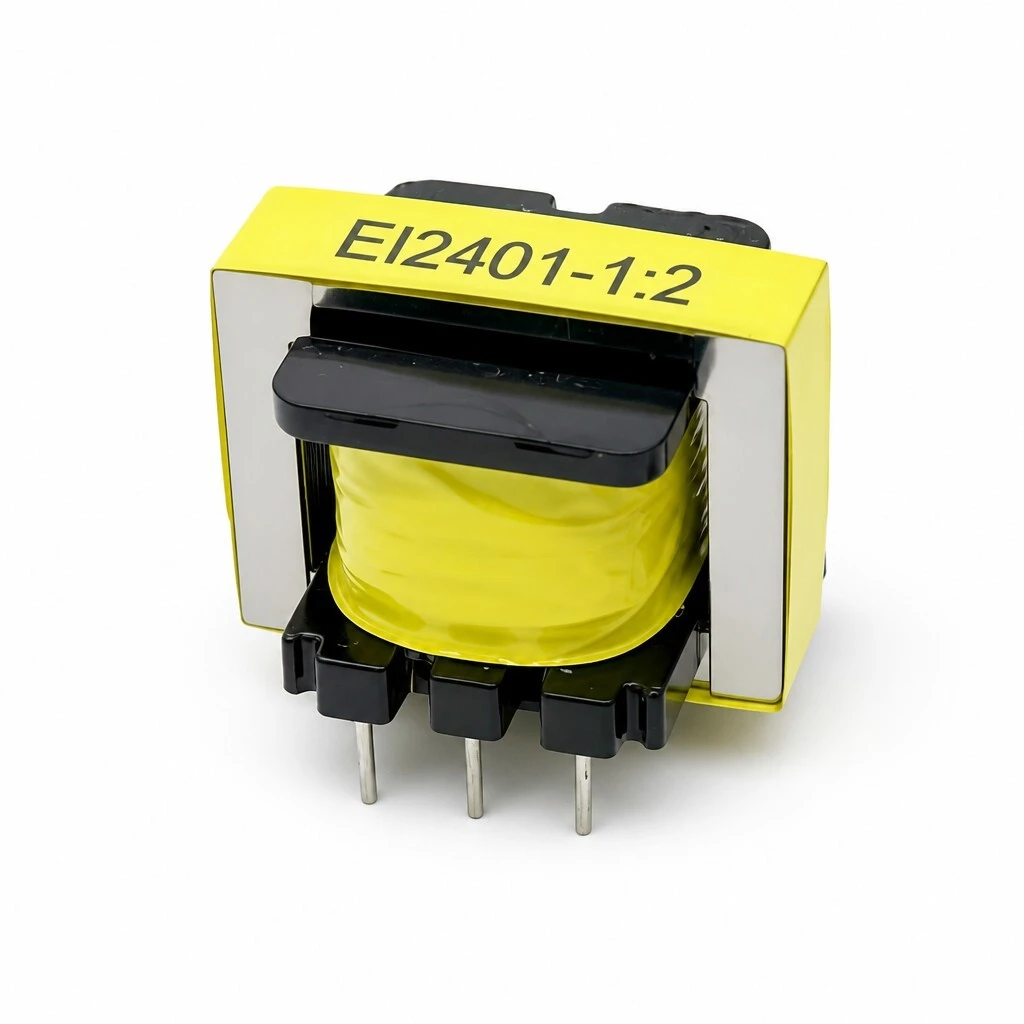
EI2401-1:2 Audio Isolation Transformer - 1:2 Step-Up, +6 dB Gain, 20 Hz-20 kHz, EI Silicon Steel, 3+3 DIP Pins, Passive Ground Loop Isolator
EI2401-1:2 passive 1:2 step-up audio isolation transformer — +6 dB gain, 20 Hz–20 kHz, EI silicon steel core, 3+3 through-hole DIP pins, no external power.
- 1:2 step-up turns ratio, approximately +6 dB voltage gain
- Galvanic isolation: breaks ground loops, removes hum and buzz
- 20 Hz – 20 kHz response with excellent common-mode rejection
- EI silicon steel lamination core, electrostatically shielded windings
- 3+3 through-hole DIP pins, centre tap on each winding; fully passive
CE certified, RoHS compliant and built under ISO 9001:2015, 100% tested for audio signal isolation and inductance.
1. Product Name
EI2401-1:2 audio isolation transformer, 1:2 step-up, approximately +6 dB voltage gain, passive galvanic isolation, 20 Hz - 20 kHz, 3+3 through-hole DIP.
Overview. The EI2401-1:2 is a passive 1:2 step-up audio isolation transformer built to break ground loops and remove hum, buzz and RF interference from professional audio signal chains. Its 1:2 turns ratio provides approximately +6 dB of voltage gain while galvanically isolating the source from the load, so equipment referenced to different ground potentials can be connected without circulating ground current.
Because the device transfers signal by magnetic coupling only, it needs no external power supply, no battery and no active circuitry. It simply passes audio from the primary winding to the secondary winding, cleanly and repeatably. The unit is wound on an EI silicon steel lamination core with electrostatically shielded windings and high-purity copper wire, insulated with flame-retardant yellow Mylar tape, and covered over 20 Hz - 20 kHz with excellent common-mode rejection, which makes it suitable for line-level studio interconnects, mixer and preamp inputs, powered monitor feeds and broadcast or PA distribution.
2. Key Features
1:2 step-up turns ratio. Approximately +6 dB of voltage gain, so the transformer lifts level as well as isolating.
Galvanic isolation. Breaks ground loops and removes the hum and buzz that comes with them.
Excellent common-mode rejection. Suppresses RFI and hum induced on both signal lines, not just one.
20 Hz - 20 kHz response. Covers the full audio band, so the part can sit anywhere in a line-level chain.
EI silicon steel lamination core. Low core loss and stable performance across the band.
Electrostatically shielded windings. An electrostatic screen between primary and secondary improves high-frequency noise rejection.
Flame-retardant Mylar insulation. Yellow Mylar tape on high-purity copper windings, for reduced heat and loss.
Fully passive design. No power supply, no battery and no active circuitry: zero power consumption and continuous, noise-free operation.
3+3 through-hole DIP pins. Three primary and three secondary pins for standard PCB mounting, with a centre tap on each winding.
The electrostatic shield is the detail that separates this part from a plain audio transformer. It is a conductive layer between primary and secondary that intercepts capacitively coupled interference before it reaches the secondary, which is where high-frequency hash from digital gear would otherwise get through. The magnetic path is unaffected, so the audio still couples at full bandwidth while the RF path is shorted to the screen.
3. Technical Specifications
| Feature | Description / specification |
|---|---|
| Primary function | Galvanic isolation for noise elimination and ground loop breaking |
| Turns ratio | 1:2 (step-up) |
| Frequency response | 20 Hz - 20 kHz (typical for audio transformers) |
| Common-mode rejection | Excellent; suppresses RFI and hum induced on both signal lines |
| Voltage gain | Approximately +6 dB, from the 1:2 step-up ratio |
| Core type | EI lamination (silicon steel) |
| Key application | Connecting audio equipment, interfaces, mixers and powered monitors to remove hum and buzz |
| Typical construction | Electrostatically shielded windings for high-frequency noise rejection |
| Operating principle | Magnetic coupling; no external power required (passive device) |
| Termination | 3+3 through-hole DIP pins (3 primary / 3 secondary) |
4. Pin Configuration (3+3 DIP)
| Winding | Pin | Designation | Function |
|---|---|---|---|
| Primary | 1 | PRI 1 | Primary winding start |
| Primary | 2 | PRI 2 | Primary winding centre tap |
| Primary | 3 | PRI 3 | Primary winding end |
| Secondary | 1 | SEC 1 | Secondary winding start |
| Secondary | 2 | SEC 2 | Secondary winding centre tap |
| Secondary | 3 | SEC 3 | Secondary winding end |
Both windings are brought out with a centre tap, so the part can be used as a plain 1:2 transformer across start and end, or as two halves per side when the centre pin is used. Wiring the windings in series or parallel is a matter of how the three pins are connected on the board; the transformer itself does not change. Identify pin 1 before assembly, because the phase of the secondary relative to the primary depends on which end is taken as start.
5. Typical Applications
Professional audio interfaces. Signal isolation and balanced audio transmission for high-quality interfaces.
Studio mixers and preamps. Isolation and noise rejection in mixing consoles and microphone preamps.
Powered monitor speakers. Clean isolated audio for accurate and reliable studio monitoring.
Broadcast and PA systems. Balanced signal transmission and isolation for professional audio installations.
In a rack, the usual fault is two units on different mains circuits, each with its own safety earth. The cable screen ties those earths together and the potential difference between them drives current through it, which is the hum. Inserting the transformer at that boundary removes the closed loop while keeping the balanced or unbalanced connection intact. The step-up ratio is a second benefit in the same part: where a consumer-level output has to drive a professional input, +6 dB of passive gain closes part of the gap without adding a powered stage.
6. Quality & Compliance
Every unit is tested for audio signal isolation and inductance before it leaves the line, so a part that does not isolate does not ship. Construction is rugged and rated for high temperature operation, and the winding is sealed under flame-retardant Mylar rather than left open.
The product is CE certified for electrical safety, RoHS compliant with a lead-free construction, and manufactured under an ISO 9001:2015 quality management system.
7. Ordering Information
The EI2401-1:2 is supplied as a PCB-mountable through-hole component for OEM, studio and audio project use. Custom turns ratios, centre-tap configurations and lead-free finishes are available on request.
Advise the target impedance, the signal level and the application, and the most suitable variant can be confirmed against the design. For a drop-in replacement, quote the existing part number and the winding configuration in use (start-to-end or with the centre tap connected).