


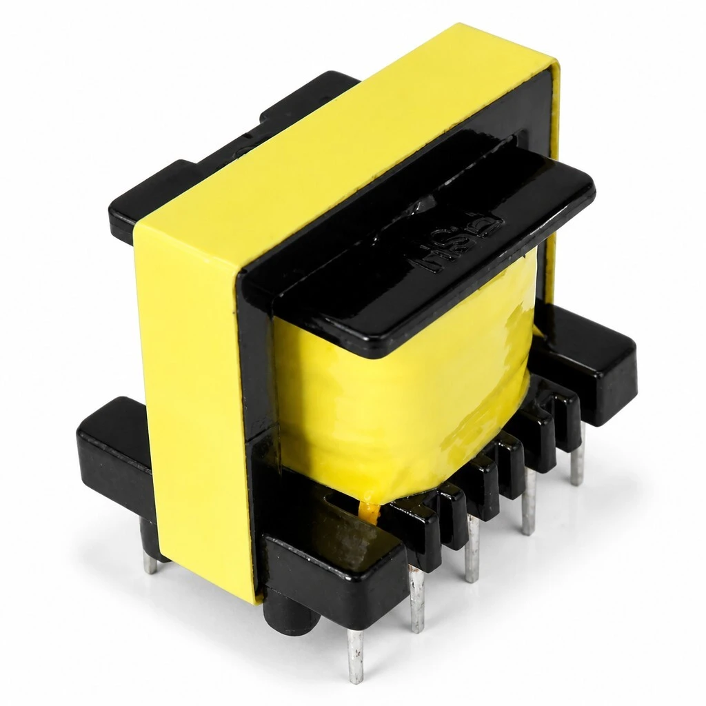
EE25-4.0H 1:1:1:1 Audio Isolation Transformer - Four Matched 4.0 H Windings | 20 Hz to 20 kHz | DIP In-Line Through-Hole | PCB Mount
The EE25-4.0H is a PCB-mountable audio isolation transformer built on the EE25 in-line bobbin platform. A 1:1:1:1 turns ratio and four matched 4.0 H windings give the part galvanic isolation between circuits, rejection of the AC hum created by system grounding, and clean coupling of balanced or unbalanced audio signals across the 20 Hz to 20 kHz range. It is used for voice and data coupling, for breaking ground loops between pieces of equipment, and for providing an isolated signal output.
- 1:1:1:1 turns ratio, four matched 4.0 H windings on pins 1-2, 3-4, 5-6 and 7-8
- Frequency range 20 Hz to 20 kHz, for voice and data coupling
- Breaks system ground loops and removes AC hum
- Reduces interference in balanced and unbalanced transmission
- DIP plug-in through-hole package, 25.5 x 18.5 x 22.0 mm, Hi-Pot 1000 V
1. Product Overview
The EE25-4.0H is a PCB-mountable audio isolation transformer built on the EE25 in-line bobbin platform. A 1:1:1:1 turns ratio and four matched 4.0 H windings give the part galvanic isolation between circuits, rejection of the AC hum created by system grounding, and clean coupling of balanced or unbalanced audio signals across the 20 Hz to 20 kHz range. It is used for voice and data coupling, for breaking ground loops between pieces of equipment, and for providing an isolated signal output.
Figure 1 — EE25-4.0H audio isolation transformer, DIP plug-in in-line package.
General information
| Item | Specification |
|---|---|
| Model / part number | EE25-4.0H |
| Transformer type | Audio isolation / coupling transformer |
| Frequency range | 20 Hz – 20 kHz |
| Package | DIP plug-in (through-hole), in-line |
| Test condition | 25 °C |
| Customization | Turns ratio, inductance and pin configuration available on request |
2. Features
- Galvanic isolation — Protects the output of the preceding equipment from being damaged.
- Voice and data coupling — Coupling transformer for voice and data lines.
- Frequency range — 20 Hz to 20 kHz.
- Ground-loop hum — Solves the AC hum produced by system grounding.
- Interference rejection — Reduces external interference in both balanced and unbalanced transmission.
- Four matched windings — 1:1:1:1 turns ratio, brought out on pins 1-2, 3-4, 5-6 and 7-8.
- PCB mounting — DIP plug-in, through-hole package for direct PCB mounting.
Figure 2 — Winding and insulation detail.
3. Advantages
- Economical — High price-performance ratio for volume production.
- Standard footprint — DIP plug-in, through-hole package, suited to standard PCB layouts and normal wave or selective soldering.
- Customizable — Customized design is available to match a specific turns ratio, inductance value or pin arrangement.
- Factory-direct supply — Stock available for immediate dispatch.
- One part, many uses — A single matched four-winding part covers a range of audio coupling and isolation requirements.
4. Applications
- Communication equipment — Isolated line and voice interfaces, inter-stage coupling.
- Car audio — Breaking ground loops between head unit, amplifier and speakers.
- Telephone and fax — Voice-band coupling and line isolation.
- Signal isolation output — Isolating an output before a long cable run.
In each case the transformer sits in the signal path so that the two sides of the circuit are isolated from one another. The direct ground connection is removed, DC offsets cannot pass, and interference picked up on the cable is attenuated instead of being added to the wanted signal.
5. Specifications
The values below are the specification of the EE25-4.0H. Electrical parameters are measured at 25 °C.
5.1 Electrical Specification (25 °C)
| Parameter | Test condition | Specification |
|---|---|---|
| Turns ratio | – | 1:1:1:1 |
| Inductance L(1-2) | 1 kHz, 0.3 V, min | 4.0 H |
| Inductance L(3-4) | 1 kHz, 0.3 V, min | 4.0 H |
| Inductance L(5-6) | 1 kHz, 0.3 V, min | 4.0 H |
| Inductance L(7-8) | 1 kHz, 0.3 V, min | 4.0 H |
| Hi-Pot | 1 mA, 60 s | 1000 V |
Inductance is quoted as a minimum value at the stated test frequency and level, and applies to each winding individually.
5.2 Outline Dimensions (unit: mm)
| Dimension | Value |
|---|---|
| Overall width, front view | 25.5 mm |
| Overall height, front view | 22.0 mm |
| Overall depth, side view | 18.5 mm |
| Pin area depth, bottom view | 12.5 mm |
| Pin pitch | 5 mm |
Winding one is brought out on pins 1-2, winding two on pins 3-4, winding three on pins 5-6 and winding four on pins 7-8. The polarity of each winding is marked on the schematic, and the four windings are matched, so a winding may be used on either the primary or the secondary side as the circuit requires.
Figure 3 — Front, side, top and bottom views of the in-line package.
Figure 4 — In-line pin row and solder termination detail.
6. Quality & Testing Assurance
- Electrical inspection — Every transformer is inspected against the electrical specification before packing: turns ratio and the inductance of all four windings at 1 kHz and 0.3 V.
- Dielectric test — Hi-Pot at 1000 V with a 1 mA leakage limit held for 60 s.
- Test condition — All testing is carried out at 25 °C.
- Packaging — Supplied in the DIP plug-in in-line package, ready for direct through-hole mounting.